


147
YORK INTERNATIONAL
FORM 201.19-NM1 (204)
Closed:
Low Ambient Mode allows the Low Ambient Cut-Out
to be programmed from 0 to 50 °F (-18 to 10°C). Val ues
above 25°F (-4°C) can be used to automatically shut
down the chiller when direct cooling methods be come
operational.
SWITCH 3: Refrigerant
Open:
The R-407C Mode MUST be selected for models us ing
refrigerant R-407C. Incorrect selection of this switch
may cause serious damage to the chiller.
Closed:
The R-22 Mode MUST be selected for models using
refrigerant type R-22. Incorrect selection of this switch
may cause serious damage to the chiller.
SWITCH 4: Unit Type
Open:
DO NOT USE THIS POSITION.
Incorrect programming may cause
damage to the chiller.
Closed:
Place the switch in the CLOSED position selects the
type of chiller as an air cooled chiller (YCAS). The
switch MUST always be in the CLOSED position.
Incorrect programming may cause
damage to the chiller.
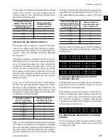
S 1 - 2 A M B I E N T C O N T R O L
L O W A M B I E N T
S 1 - 3 R E F R I G E R A N T
R - 4 0 7 C
S 1 - 3 R E F R I G E R A N T
R - 2 2
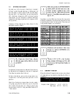
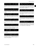
Dip Switch Physical Location and Setting
FIG. 49
–
ENLARGED PHOTOGRAPH OF DIP
SWITCHES ON MICROPROCESSOR BOARD
LD03511A
LD03511B
“OPEN” Position:
Left side of switch
pushed in
“CLOSED” Position:
Right side of switch
pushed in
8
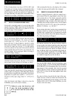
S 1 - 4 Y C W S
S 1 - 4 Y C A S
SWITCH 5: Motor Current Average option
(start-up)
Open:
DO NOT USE THIS POSITION.
Nuisance trips at start-up could result.
S 1 - 5 M O T O R C U R R E N T
A V E R A G I N G E N A B L E D
028981-G
Содержание YCAS0130
Страница 45: ...45 YORK INTERNATIONAL FORM 201 19 NM1 204 5 This page intentionally left blank...
Страница 47: ...47 YORK INTERNATIONAL FORM 201 19 NM1 204 6 This page intentionally left blank...
Страница 63: ...63 YORK INTERNATIONAL FORM 201 19 NM1 204 This page intentionally left blank 7...
Страница 73: ...73 YORK INTERNATIONAL FORM 201 19 NM1 204 LD09239 FIG 22B CONTROL PANEL COMPONENT LOCATION 7...
Страница 75: ...75 YORK INTERNATIONAL FORM 201 19 NM1 204 7 LEGEND LD09241...
Страница 76: ...76 YORK INTERNATIONAL FORM 201 19 NM1 204 Technical Data LD03282 LD03283 2 ACE MOTOR PROTECTOR MODULE LD03284...
Страница 77: ...77 YORK INTERNATIONAL FORM 201 19 NM1 204 7 CONNECTION DIAGRAM SYSTEM WIRING LD09242...
Страница 78: ...78 YORK INTERNATIONAL FORM 201 19 NM1 204 Technical Data COMPRESSOR TERMINAL BOX LD09243...
Страница 79: ...79 YORK INTERNATIONAL FORM 201 19 NM1 204 7 LD09373 ELEMENTARY DIAGRAM CONTROL CIRCUIT...
Страница 81: ...81 YORK INTERNATIONAL FORM 201 19 NM1 204 7 This page intentionally left blank...
Страница 113: ...113 YORK INTERNATIONAL FORM 201 19 NM1 204 COMPRESSOR COMPONENTS CONT D FIG 41 COMPRESSOR COMPONENTS LD03670 7...
Страница 121: ...121 YORK INTERNATIONAL FORM 201 19 NM1 204 7 This page intentionally left blank...
Страница 193: ...193 YORK INTERNATIONAL FORM 201 19 NM1 204 8 This page intentionally left blank...