


177
YORK INTERNATIONAL
FORM 201.19-NM1 (204)
8
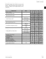
The chiller is equipped with 8 or 10 condenser fans, with
4 or 5 fans per system as given below. Fan control is
via Outside Ambient Temperature (OAT) and Discharge
Pressure (DP). There are 4 or 5 stages of fan control,
utilizing 3 outputs per system. The fan stages will work
according to Table 3 and 4 depending on the number of
fans per system. There will be a variable delay between
all fan stages. The delay between turning on fan stages
is based on the ambient temperature. The time is ramped
from 30 seconds at 10ºF (-12.2ºC) to 5 seconds at 60ºF
(15.6ºC) (time delay = (35 - (oat/2)).
Condenser fan ON conditions are governed solely by the
Discharge Pressure (DP). When the DP rises above 230
PSIG, fan stage 1 is activated. From here, subsequent
fan stages are activated as the DP rises in increments of
10 - 20 PSIG. The system will remain at the highest fan
stage reached unless the OFF conditions are satis
fi
ed.
Condenser fan OFF conditions are governed by both
the DP and OAT. Fan staging will be decreased from
the highest fan stage reached if both the DP and OAT
requirements are met. For example, if a system is at
a fan stage of 4, and the DP falls under 205 PSIG and
the OAT drops below 75ºF (24ºC), the fan stage will be
reduced to 3.
FIG. 51 –
CONDENSER FAN LAYOUT FOR DXST 2
COMPRESSOR UNITS
LD03676
Tables 3 and 4 describe fan operation and contactor data
for the fans involved in each fan stage. SYS 1 uses relay
board #1. SYS 2 uses relay board #2.
YCAS0130, 0140, 0150, 0160, 0170 and 0190 models
have 4 condenser fans/system:
8.8 CONDENSER FAN CONTROL
Содержание YCAS0130
Страница 45: ...45 YORK INTERNATIONAL FORM 201 19 NM1 204 5 This page intentionally left blank...
Страница 47: ...47 YORK INTERNATIONAL FORM 201 19 NM1 204 6 This page intentionally left blank...
Страница 63: ...63 YORK INTERNATIONAL FORM 201 19 NM1 204 This page intentionally left blank 7...
Страница 73: ...73 YORK INTERNATIONAL FORM 201 19 NM1 204 LD09239 FIG 22B CONTROL PANEL COMPONENT LOCATION 7...
Страница 75: ...75 YORK INTERNATIONAL FORM 201 19 NM1 204 7 LEGEND LD09241...
Страница 76: ...76 YORK INTERNATIONAL FORM 201 19 NM1 204 Technical Data LD03282 LD03283 2 ACE MOTOR PROTECTOR MODULE LD03284...
Страница 77: ...77 YORK INTERNATIONAL FORM 201 19 NM1 204 7 CONNECTION DIAGRAM SYSTEM WIRING LD09242...
Страница 78: ...78 YORK INTERNATIONAL FORM 201 19 NM1 204 Technical Data COMPRESSOR TERMINAL BOX LD09243...
Страница 79: ...79 YORK INTERNATIONAL FORM 201 19 NM1 204 7 LD09373 ELEMENTARY DIAGRAM CONTROL CIRCUIT...
Страница 81: ...81 YORK INTERNATIONAL FORM 201 19 NM1 204 7 This page intentionally left blank...
Страница 113: ...113 YORK INTERNATIONAL FORM 201 19 NM1 204 COMPRESSOR COMPONENTS CONT D FIG 41 COMPRESSOR COMPONENTS LD03670 7...
Страница 121: ...121 YORK INTERNATIONAL FORM 201 19 NM1 204 7 This page intentionally left blank...
Страница 193: ...193 YORK INTERNATIONAL FORM 201 19 NM1 204 8 This page intentionally left blank...