


136
YORK INTERNATIONAL
FORM 201.19-NM1 (204)
2. STATUS KEY: GENERAL STATUS MESSAGES & FAULT WARNINGS
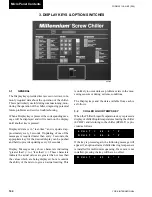
2.1 GENERAL
Pressing the Status key displays the current chiller or
individual system operational status. The messages dis-
played include running status, cooling demand, fault
sta tus, external cycling device status, load limiting, and
anti-recycle timer status. The display will show one mes-
sage relating to the “highest priority” information as
de ter mined by the microprocessor.
For individual system status or fault messages, the
dis play shows information for up to two refrigerant
sys tems.
The main categories of messages available using the
Status key are:
2.2 General Status Messages
2.3 Unit Warnings
2.4 Anticipation Control Status Messages
2.5 Chiller Fault Status Messages
2.6 System Fault Status Messages
These messages are described in detail below, with ex-
am ples of each display. In each example “#” is used as
applicable to represent the system number where mes-
sag es apply to individual systems.
2.2
GENERAL STATUS MESSAGES
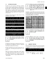
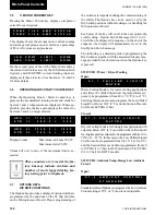
Unit Switch OFF:
This message indicates that the Chiller ON / OFF Switch
on the Control Panel is in the OFF position which will
not allow the chiller to run.
Schedule Shutdown:
This message indicates that the that the chiller has been
shut down by the daily schedule programmed into the
Clock - Set Schedule / Holiday (Section 7.3).
Compressors Running:
This message indicates that the respective compressor
is running due to demand.
Remote Controlled Shutdown:
This message indicates that either an ISN or RCC (Re-
mote Control Center) has turned the unit OFF through
the RS-485 port.
U N I T S W I T C H O F F
S H U T D O W N
D A I L Y S C H E D U L E
S H U T D O W N
S Y S # C O M P R U N N I N G
S Y S # C O M P R U N N I N G
R E M O T E C O N T R O L L E D
S H U T D O W N
29023A
Micro Panel Contents
Содержание YCAS0130
Страница 45: ...45 YORK INTERNATIONAL FORM 201 19 NM1 204 5 This page intentionally left blank...
Страница 47: ...47 YORK INTERNATIONAL FORM 201 19 NM1 204 6 This page intentionally left blank...
Страница 63: ...63 YORK INTERNATIONAL FORM 201 19 NM1 204 This page intentionally left blank 7...
Страница 73: ...73 YORK INTERNATIONAL FORM 201 19 NM1 204 LD09239 FIG 22B CONTROL PANEL COMPONENT LOCATION 7...
Страница 75: ...75 YORK INTERNATIONAL FORM 201 19 NM1 204 7 LEGEND LD09241...
Страница 76: ...76 YORK INTERNATIONAL FORM 201 19 NM1 204 Technical Data LD03282 LD03283 2 ACE MOTOR PROTECTOR MODULE LD03284...
Страница 77: ...77 YORK INTERNATIONAL FORM 201 19 NM1 204 7 CONNECTION DIAGRAM SYSTEM WIRING LD09242...
Страница 78: ...78 YORK INTERNATIONAL FORM 201 19 NM1 204 Technical Data COMPRESSOR TERMINAL BOX LD09243...
Страница 79: ...79 YORK INTERNATIONAL FORM 201 19 NM1 204 7 LD09373 ELEMENTARY DIAGRAM CONTROL CIRCUIT...
Страница 81: ...81 YORK INTERNATIONAL FORM 201 19 NM1 204 7 This page intentionally left blank...
Страница 113: ...113 YORK INTERNATIONAL FORM 201 19 NM1 204 COMPRESSOR COMPONENTS CONT D FIG 41 COMPRESSOR COMPONENTS LD03670 7...
Страница 121: ...121 YORK INTERNATIONAL FORM 201 19 NM1 204 7 This page intentionally left blank...
Страница 193: ...193 YORK INTERNATIONAL FORM 201 19 NM1 204 8 This page intentionally left blank...