FORM 150.66-NM3
ISSUE DATE: 09/25/2020
135
JOHNSON CONTROLS
SECTION 8 - UNIT OPERATION
8
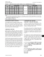
EVAPORATOR HEATER CONTROL
The evaporator heater is controlled by ambient air tem-
perature. When the ambient temperature drops below
40°F (4.4
°C)
the heater is turned on. When the tem-
perature rises above 45°F (7.2
°C)
the heater is turned
off. An under voltage condition will keep the heater off
until full voltage is restored to the system.
PUMPDOWN CONTROL
Each system has a pump-down feature upon shut-off.
Manual pumpdown from the keypad is not possible. On
a non-safety, non-unit switch shutdown, all compressors
but one in the system will be shut off. The LLSV or EEV
will also be turned off. The final compressor will be al
-
lowed to run until the suction pressure falls below the
cutout, or for 180 seconds, whichever comes first.
The EEV pilot solenoid is also used as a low superheat
safety device when the EEV is selected as the expan-
sion valve type. While the system is running and not in
a pumpdown mode, the EEV pilot solenoid will close
if the suction superheat falls below 4°F. The EEV pi-
lot solenoid will open again when the superheat rises
above 7.0°F. This safety device is ignored for the first
30 seconds of system run time. If the EEV pilot sole-
noid is closed 10 times in 2 minutes on the safety de-
vice, the low superheat safety will be triggered.
CONDENSER FAN CONTROL
(YCAL0041 – YCAL0071 CHILLERS)
Condenser fan operation must be programmed with the
Options key under “Fan Control.” Condenser fan con-
trol can be selected for Ambient Temp. and Discharge
Pressure, or Discharge Pressure only.
The condenser fan control by “Ambient Temperature
and Discharge Pressure” is a feature that is integral to
the standard software control. If the optional discharge
transducer is not installed, the condenser fans will op-
erate based on outdoor ambient temperature only. See
Table 22.
The condenser fan control by “Discharge Pressure” is
a feature that can be selected if the discharge pressure
transducer is installed and fan recycling is not a con-
cern. Fan control by discharge pressure will work ac-
cording to Table 23. The fan control on-pressure and
fan differential off-pressure are programmable under
the PROGRAM key.
A low ambient kit MUST be installed
when “AMBIENT CONTROL LOW
AMBIENT” is selected under the OP
-
TIONS key.
Compressor damage could occur if
programming does not match installed
hardware.
LEAD SYSTEM
LAG SYSTEM
STEP
COMP 1
COMP 2
-
COMP 1
COMP 2
-
0
OFF
OFF
-
OFF
OFF
-
1
ON + HG
OFF
-
See NOTE 1
OFF
OFF
-
2
ON
OFF
-
OFF
OFF
-
3
ON
OFF
-
See NOTE 2
ON
OFF
-
4
ON
ON
-
See NOTE
3
OFF
OFF
-
5
ON
ON
-
ON
OFF
-
6
ON
ON
-
ON
ON
-
NOTES
1. Step is Hot Gas Bypass and is skipped when loading occurs. Hot Gas Bypass operation is inhibited during pumpdown. For Leaving Chilled
Liquid Control the Hot Gas Bypass solenoid is energized only when the lead compressor is running and the LWT < SP, the Hot Gas Bypass
solenoid is turned off whenthe LWT > SP + CR/2.
2. Step 3 is skipped when loading occurs.
3. Step 4 is skipped when unloading occurs.
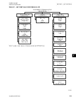
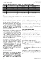
TABLE 21 – RETURN CHILLED LIQUID CONTROL FOR 4 COMPRESSORS (6 STEPS)
Содержание YCAL Series
Страница 4: ...JOHNSON CONTROLS 4 FORM 150 66 NM3 ISSUE DATE 09 25 2020 THIS PAGE INTENTIONALLY LEFT BLANK...
Страница 16: ...JOHNSON CONTROLS 16 FORM 150 66 NM3 ISSUE DATE 09 25 2020 THIS PAGE INTENTIONALLY LEFT BLANK...
Страница 130: ...JOHNSON CONTROLS 130 FORM 150 66 NM3 ISSUE DATE 09 25 2020 THIS PAGE INTENTIONALLY LEFT BLANK...
Страница 144: ...JOHNSON CONTROLS 144 FORM 150 66 NM3 ISSUE DATE 09 25 2020 THIS PAGE INTENTIONALLY LEFT BLANK...
Страница 173: ...FORM 150 66 NM3 ISSUE DATE 09 25 2020 173 JOHNSON CONTROLS 10 NOTES...


