background image

5532522-UIM-B-0619

Johnson Controls Ducted Systems

15

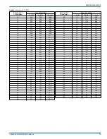
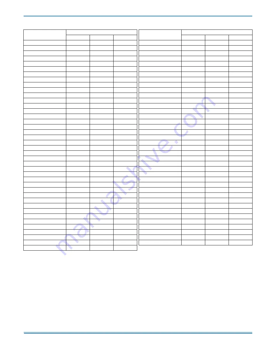
Table 8: 

Gas Rate (CU FT/HR)

Seconds For 
1 Revolution

Size of Test Dial

Seconds For 
1 Revolution

Size of Test Dial

1 Cu Ft

2 Cu Ft

5 Cu Ft

1 Cu Ft

2 Cu Ft

5 Cu Ft

10

360

720

1800

50

72

144

360

11

327

655

1636

51

71

141

355

12

300

600

1500

52

69

138

346

13

277

555

1385

53

68

136

340

14

257

514

1286

54

67

133

333

15

240

480

1200

55

65

131

327

16

225

450

1125

56

64

129

321

17

212

424

1059

57

63

126

316

18

200

400

1000

58

62

124

310

19

189

379

947

59

61

122

305

20

180

360

900

60

60

120

300

21

171

343

857

62

58

116

290

22

164

327

818

64

56

112

281

23

157

313

783

66

54

109

273

24

150

300

750

68

53

106

265

25

144

288

720

70

51

103

257

26

138

277

692

72

50

100

250

27

133

267

667

74

48

97

243

28

129

257

643

76

47

95

237

29

124

248

621

78

46

92

231

30

120

240

600

80

45

90

225

31

116

232

581

82

44

88

220

32

113

225

563

84

43

86

214

33

109

218

545

86

42

84

209

34

106

212

529

88

41

82

205

35

103

206

514

90

40

80

200

36

100

200

500

92

39

78

196

37

97

195

486

94

38

76

192

38

95

189

474

96

38

75

188

39

92

185

462

98

37

74

184

40

90

180

450

100

36

72

180

41

88

176

439

102

35

71

178

42

86

172

429

104

35

69

173

43

84

167

419

106

34

68

170

44

82

164

409

108

33

67

167

45

80

160

400

110

33

65

164

46

78

157

391

112

32

64

161

47

76

153

383

116

31

62

155

48

75

150

375

120

30

60

150

49

73

147

367

Содержание TL8E

Страница 1: ...ment closet alcove attic recreation room or garage and are also ideal for commercial applications All units are factory assembled wired and tested to assure safe dependable and economical installation...

Страница 2: ...talling and servicing heating equipment can be hazardous due to the electrical components and the gas fired components Only trained and qualified personnel should install repair or service gas heating...

Страница 3: ...spection by the carrier s agent should be made in writing Also before installation the unit should be checked for screws or bolts which may have loosened in transit There are no shipping or spacer bra...

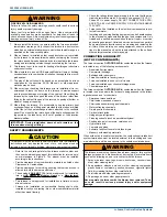
Страница 4: ...rizontal configuration then extra 2 minimum spacing may be needed to ensure against drain pan distortion On all installations without a coil a removable access panel is recom mended in the outlet duct...

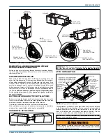
Страница 5: ...rt with required service accessibility HORIZONTAL APPLICATION ATTIC INSTALLATION This appliance is certified for line contact when the furnace is installed in the horizontal left or right position The...

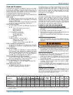
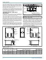
Страница 6: ...s must be level to ensure proper and quiet fur nace operation When suspending the furnace use a secure platform constructed of plywood or other building materials secured to the floor or ceiling joist...

Страница 7: ...minimum sizes listed in these instructions and in the codes The furnace rating plate and the instructions in this section specify the type of gas approved for this furnace only use those approved gase...

Страница 8: ...latest edition and all local codes The furnace shall be installed so that the electrical components are protected from water FIGURE 9 Gas Piping GROUND UNION DRIP LEG MANUAL SHUT OFF VALVE GROUND UNIO...

Страница 9: ...set in the OFF position and the main electrical source disconnected connect the thermostat wiring from the wiring connections on the thermostat to the low voltage terminal block on the integrated furn...

Страница 10: ...rmostat Chart Single Stage HP with Single Stage Furnaces 6LQJOH 6WDJH R1R XUQDFH 6LQJOH 6WDJH HDW 3XPS 6HFRQG 6WDJH HDW DQ 5 9ROW RW LUVW 6WDJH HDW 9ROW RPPRQ 9ROW RPPRQ 5 9ROW RW 6HFRQG 6WDJH RPSUHVV...

Страница 11: ...FURNACE IS NOT TO BE VENTED INTO AN UNLINED MASONRY CHIMNEY 2 This furnace must be vented into a fire clay tile lined masonry chim ney only if a source of dilution air is provided such as by common v...

Страница 12: ...ind Such means shall not reduce the required free area of the air supply opening 7 An air supply inlet opening from the outdoors shall be located not less than 12 30 5 cm above the outside grade level...

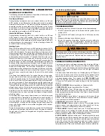
Страница 13: ...d that the ground union be loosened until the odor of gas is detected When gas is detected immediately retighten the union and check for leaks Allow five minutes for any gas to dissipate before contin...

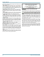
Страница 14: ...occur as follows a The induced draft blower will start and will run for several sec onds in order to bring fresh combustion air into the combustion chamber Then the induced draft blower will shut off...

Страница 15: ...22 164 327 818 64 56 112 281 23 157 313 783 66 54 109 273 24 150 300 750 68 53 106 265 25 144 288 720 70 51 103 257 26 138 277 692 72 50 100 250 27 133 267 667 74 48 97 243 28 129 257 643 76 47 95 237...

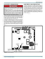
Страница 16: ...n gas valve 2 Turn gas and electrical supplies on and follow the operating instruc tions to place the unit back in operation 3 Adjust manifold pressure by adjusting gas valve regulator screw for the a...

Страница 17: ...to 120 seconds The fan off setting must be long enough to adequately cool the furnace but not so long that cold air is blown into the heated space The fan off timing may be adjusted by positioning th...

Страница 18: ...alve This is an automatic reset control that provides over temperature protection due to reduced airflow This may be caused by 1 A dirty filter 2 If the indoor fan motor should fail 3 Too many supply...

Страница 19: ...condition is not corrected the ignition control will lock out for 60 minutes During burner operation a momentary loss of power for 50 milliseconds or longer will de energize the gas valve When the pow...

Страница 20: ...e if a temporary condition exists causing a furnace malfunction An example of this is a temporary interruption in gas supply that would prevent the furnace from lighting The control will keep trying t...

Страница 21: ...FICE BURNER SIGHT GLASS OVAL 2 Req d GASKET FOAM Door 1 5 ft req d GASKET INTAKE PAN PLUG VENT HOLE BRACKET DOOR WIRING HARNESS FERRULE 3 Req d GROMMET 3 Req d MOTOR MOUNT TUBING SILICON DIAGRAM WIRIN...

Страница 22: ...5532522 UIM B 0619 22 Johnson Controls Ducted Systems SECTION XI WIRING DIAGRAM FIGURE 20 Wiring Diagram...

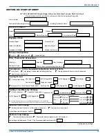
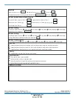
Страница 23: ...stallation Instructions and Local Code Gas piping is connected including drip leg Supply plenum and return air are connected Filter Size Vent system is connected Thermostat wiring is complete Thermost...

Страница 24: ...ure in w c Return Static in w c after Air Side Heating Air Side Cooling Air Side Continuous Fan Clean Up Give owner the owner s manual provided Explain thermostat use and programming if applicable to...

Отзывы: