background image

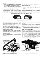
9.  Reinstall the blower assembly. Replace mounting screws

that hold the blower assembly to the front portion of the
blower deck. Two mounting screws used on the sides of
the blower are used for shipping purposes only, and are
not necessary after the furnace has been installed.

10.  Reinstall the control box and reconnect the wiring harness

plugs.

11.  Replace the access doors and restore the electrical supply

to the unit.

Burner Removal/Cleaning

The main burners should be checked periodically for dirt
accumulation.

If cleaning is required, follow this procedure:

1.  Turn off the electrical power to the unit.

2.  Remove the access door.

3.  Remove the igniter.

4.  Turn off the gas supply at the external manual shutoff valve

and loosen the ground union joint.

5.  Remove the airshield.

6.  Remove the four screws that hold the burner assembly to

the vest panel and remove the assembly.

7.  Remove burners from the burner assembly.

8.  Burners may be cleaned by rinsing in hot water.

9.  Reassemble the burners in the reverse order, making sure

the burner shield is tightened securely in place.

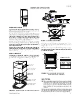
Cleaning the Heat Exchanger

1.  Turn off the main manual gas valve external to the furnace.

2.  Turn off electrical power to the furnace.

3.  Remove the upper access door and remove airshield

4.  Disconnect wires from HSI sensor, rollout switch and HSI

igniter. Remove igniter carefully, as it is easily broken.

5.  Remove the screws that hold the burner assembly to the

vestibule panel and remove the assembly. The lower
portion of the heat exchanger will now be exposed.

6.  Remove inducer blower and motor at the top of the fur-

nace. Remove upper plate.

7.  The upper portion of the heat exchanger is now exposed.

8.  With a long flexible wire brush, clean inside each tube at

both the top and bottom. The brush must pass around the
rear heat exchanger tubes. Vacuum loose scale and dirt
from each tube.

9.  Clean - vacuum all burners.

10.  Replace all components in reverse order. Reconnect all

wiring.

11.  Restore electrical power and gas supply to the furnace.

12. Check furnace operation.

TROUBLESHOOTING

The following visual checks should be made before trou-
bleshooting:

1.  Check to see that the power to the furnace and the ignition

control module is ON.

2.  The manual shutoff valves in the gas line to the furnace

must be open.

3.  Make sure all wiring connections are secure.

4.  Review the sequence of operation.

Start the system by setting the thermostat above room
temperature. Observe the system’s response. Then use the
Troubleshooting tables in this manual to check the system’s
operation.

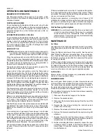
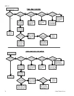
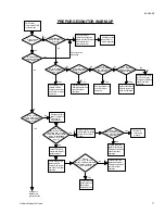
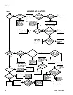
Use the troubleshooting table by reading the upper left-hand
box and then following the instructions in each box. If the
condition described in the box is true (yes answer), go down to
the next box. If the condition is not true (no answer), go to the
box to the right.

Continue checking and answering the questions in the boxes until
the problem is explained and corrective action is described. After
any maintenance or repair, the troubleshooting sequence can be
repeated until normal system operation is obtained.

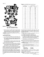
FURNACE CONTROL DIAGNOSTICS

The furnace has built-in, self diagnostic capability. If a system
problem occurs, a fault code is shown by a blinking LED on the
blower deck. It is located just to the right of the wiring harness
plug. To view the LED, remove the top furnace panel. DO NOT
remove the furnace blower compartment panel OR turn off
furnace power as either action will clear the control’s memory
of the fault.

The control continuously monitors its own operation and the
operation of the system. If a failure occurs, the LED will indicate
the failure code. If the failure is internal to the  control, the light
will stay on continuously. In this case, the entire control should
be replaced as the control is not field repairable.

If the sensed failure is in the system (external to the control),
the LED will flash in the following flash-pause sequences to
indicate failure status (each flash will last approximately 1/4
second, each pause will last approximately 2 seconds).

1 flash, then pause........

System lockout

2 flashes, then pause ....

Pressure switch stuck closed

3 flashes, then pause ....

Pressure switch stuck open

4 flashes, then pause ....

Open high limit switch

5 flashes, then pause ....

Open rollout switch

Continuous flashing 
  (no 

pause)..............

Flame has been sensed when


no 

flame 

should 

be 

present


(no 

call 

for 

heat)

LED on -not flashing......

Faulty control

The LED will also flash once at power-up. If the control is locked
out, it may be reset by momentary power interruption. Either
the 24v thermostat or line voltage may be interrupted for 30
seconds or longer.

WARNING: Never jump pressure switch to allow furnace op-

eration. To do so will allow furnace to operate under
potentially hazardous conditions.

WARNING:  Do not try to repair controls. Replace defective

controls with UPG Source 1 Parts.

WARNING: Never adjust pressure switch to allow furnace

operation.

650.69-N3

Unitary Products Group

15

Содержание P2DP Series

Страница 1: ...as supplier s instructions If you cannot reach your gas supplier call the fire department IAMON 80 D D UPFLOW MULTI POSITION GAS FIRED FURNACES INDUCED DRAFT STYLE G INSTALLATION INSTRUCTION Supersedes 650 69 N3Y 1294 650 69 N3Y 1095 035 13581 CAUTION THIS PRODUCT MUST BE INSTALLED IN STRICT COM PLIANCE WITH THE ENCLOSED INSTALLATION IN STRUCTIONSANDANY APPLICABLELOCAL STATE AND NATIONALCODESINCLU...

Страница 2: ...ired appli ances as allowed by the National Fuel Gas Code NFPA 54 ANSI Z223 1 latest edition WARNING This appliance is not to be used for temporary heating of buildings or structures under construction WARNING Do not install this furnace in a corrosive or con taminated atmosphere WARNING Do not install this furnace in a mobile home or recreational vehicle WARNING Furnaces shall not be installed di...

Страница 3: ...space The openings shall com municate freely with interior areas having adequate infil tration from the outside NOTE At least 100 square inches free area shall be used for each opening 2 Air Source from Outdoors Two permanent openings one within 12 inches of the top of the confined space and one within 12 inches of the bottom shall communicate directly or by means of ducts with the outdoors or to ...

Страница 4: ...P2MPD20 11201 35 65 180 3 4 11 x 10 13 8 15 14 16 X 25 25 X 27 163 Variable Speed Blower Models P2MPV12N06401 25 55 180 1 2 10 x 7 12 15 14 16 X 25 16 X 27 119 P2MPV14N08001 30 60 180 1 2 10 x 9 12 15 14 16 X 25 20 X 27 135 P2MPV20N08001 30 60 180 1 11 x 10 12 15 14 16 X 25 20 X 27 140 NOTES 1 Filters may be provided as an accessory or field supplied High velocity type must be used 2 All airflow o...

Страница 5: ...13 8 15 14 2 14 X 20 168 Model designator may be N for standard units or L for factory built low NOx units Model A B C D P2DPD10 04801 16 1 4 14 15 3 P2DPD12 06401 16 1 4 14 15 4 P2DPD12 08001 22 1 4 20 21 4 P2DPD16 08001 22 1 4 20 21 4 P2DPD16 09201 22 1 4 20 21 4 P2DPD20 10401 26 1 4 24 25 4 All dimensions are in inches and are approximate C 3 4 28 1 2 A 20 40 FRONT LEFT SIDE RIGHT SIDE GAS INLE...

Страница 6: ...nal Fuel Gas Code ANSI Z223 1 or the CAN CGA B149 Installation Codes and these in structions Determine that there is no blockage or restric tion leakage corrosion or other deficiencies which could cause an unsafe condition 3 Insofar as is practical close all building doors and windows and all doors between the space in which the appliance s connected to the venting system are located and other spa...

Страница 7: ...Filter and Mounting System A return air filter grille or duct mounted filter may be provided The following minimum sizes are recom mended NOTE Air velocity through throw away type filters may not exceed 300 feet per minute All velocities over this require the use of high velocity filters Side Return Locate and knock out the square corner locaters These indi cate the size of the cutoff to be made i...

Страница 8: ...sing rod pipe or straps refer to Physical Data Page 4 for furnace weights to determine suitable means of suspension Angle supports should be placed at the supply air end and near the blower deck Units may also be suspended by using straps or other material at the same location All four suspension points must be level to ensure quiet furnace operation 1 4 SUPPORT ROD ANGLE IRON BRACKET 6 MIN BETWEE...

Страница 9: ...fied on the rating plate or a matching cooling coil Follow the instructions with the combustible floor base acces sory The floor opening dimensions for the floor base are shown in Figure 10 This base can be replaced with a matching cooling coil prop erly sealed to prevent leaks Follow the cooling coil instructions for installing the plenum GAS PIPING NOTE An accessible manual shutoff valve must be...

Страница 10: ... with the provisions of the National Electrical Code ANSI NFPA No 70 latest edition Canadian Electric Code C22 1 Part 1 latest edition and or local codes Electrical wires which are field installed shall conform with the tempera ture limitation for 63 F 35 C rise wire when installed in accord ance with instructions Specific electrical data is given on the furnace rating plate Provide a power supply...

Страница 11: ...ot rely upon the interlock switch as a main power disconnect Rollout Switch Controls These controls are mounted on the burner assembly If the temperature in the burner compartment exceeds its set point the igniter control and the gas valve are de energized This is a manual reset control and must be reset before operation can continue The operation of this control indicates a malfunction in the com...

Страница 12: ...ut is not within 2 of the furnace rating with allowance being made for the permissible range of the regula tor setting 0 3 inches W C replace the orifice spuds with spuds of the proper size CAUTION Be sure to relight any gas appliances that were turned off at the start of this input check ADJUSTMENT OF MANIFOLD GAS PRESSURE 1 Turn gas off at main gas valve Remove 1 8 plug in the main gas valve bod...

Страница 13: ...o use the same speed tap for heating and cooling the heat terminal and cool terminal must be connected using a jumper wire and connected to the desired motor lead Place all unused motor leads on Park terminals Two are provided CAUTION Do not energize more than one motor speed at a time or damage will result ADJUSTMENT OF FAN OFF CONTROL SETTINGS This furnace is equipped with a time on time off hea...

Страница 14: ...ll begin and the burner will operate normally if the gas supply returns or the fault condition is corrected prior to the last ignition attempt Otherwise the control will lockout The control will repeat the ignition sequence for a total of four recycles if flame is lost within the first 10 seconds of estab lishment If flame is established for more than 10 seconds after ignition the control will cle...

Страница 15: ...on Start the system by setting the thermostat above room temperature Observe the system s response Then use the Troubleshooting tables in this manual to check the system s operation Use the troubleshooting table by reading the upper left hand box and then following the instructions in each box If the condition described in the box is true yes answer go down to the next box If the condition is not ...

Страница 16: ...stat G to R contacts close FAN ONLY CHECK COOLING CYCLE CHECK Does the circulator blower energize at cool speed Is 25 volts present across terminals Y C Is 25 volts present across terminals R C Is 25 volts present across secondary of transformer Is 120 volts present across primary of transformer Energize module check for 120 v across circulator cool CIR neutral Energize system Does circulator blow...

Страница 17: ...e or circuit breaker System is functioning properly Connect voltmeter across terminals of igniter harness Check wiring If ok replace thermostat Energize system and check for proper operation No No Yes Yes No Yes No PREPURGE IGNITOR WARM UP Check for proper operation on pressure switch contacts Replace inducer blower or pressure switch Energize system and check for proper operation Pressure switch ...

Страница 18: ...resent Check wiring If OK replace module Energize and check for proper operation Reverse 120 V hot and neutral line wires Less than 30 V Unplug circulator blower wires and connect voltmeter across terminals Disconnect electric power to system at main fuse or circuit breaker System is functioning properly Check wiring If OK replace module Energize the system and check for proper operation Replace c...

Страница 19: ...WIRING DIAGRAM UPFLOW MULTI SPEED MODELS NOTE The furnace s control system depends on correct polarity of the power supply 650 69 N3 Unitary Products Group 19 ...

Страница 20: ...WIRING DIAGRAM DOWNFLOW MODELS NOTE The furnace s control system depends on correct polarity of the power supply 650 69 N3 20 Unitary Products Group ...

Страница 21: ... 2110 2004 1913 1797 1581 MED 2027 1986 1945 1917 1877 1820 1763 1653 1558 1445 LOW 1349 1327 1312 1281 1233 1150 1078 P2MPD20N11201 See Notes 6 7 HIGH 2204 2154 2081 2055 2002 1933 1843 1706 1545 1409 MED 1805 1779 1758 1715 1656 1579 1507 1395 1292 LOW 1451 1451 1423 1377 1284 1201 1095 P9MPD08N03201 See Note 1 HIGH 1175 1020 995 890 835 740 685 MED 950 920 885 810 710 650 605 LOW 625 605 595 58...

Страница 22: ...DPD16 08001 HIGH 2043 2000 1893 1823 1726 1627 1503 1382 1249 1134 MED 1706 1655 1593 1533 1450 1366 1265 1163 1062 950 LOW 1452 1406 1373 1317 1245 1174 1112 1025 935 817 P2DPD16 09201 HIGH 2053 1977 1899 1817 1725 1623 1519 1401 1265 1120 MED 1711 1667 1606 1530 1458 1383 1284 1184 1066 951 LOW 1460 1434 1407 1363 1310 1232 1137 1064 964 854 P2DPD20 10401 HIGH 2330 2248 2177 2103 2024 1910 1789 ...

Страница 23: ...NOTES 650 69 N3 Unitary Products Group 23 ...

Страница 24: ...ry Products Group P O Box 1592 York Pennsylvania USA 17405 1592 Subject to change without notice Printed in U S A Copyright by York International Corporation 1994 All Rights Reserved Code SBY 650 69 N3Y 1294 ...

Отзывы: