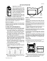
Upflow furnaces may be installed horizontally with the supply
airflow toward the left or right by laying the unit on the left or
right panel. Do not install the unit on the rear panel.. After
determining the best orientation, lay the unit on top of the
shipping carton to protect the finish.
The appropriate electrical knock-outs for power wiring, control
wiring and gas piping should be removed at this time.
When in the horizontal position, return air may enter through
the end of the unit, the bottom panel, the top panel or any
combination of these openings. Return air may not be con-
nected into the rear panel of the unit.
To convert the upflow model furnace to open bottom, refer to
the Upflow Application - Bottom Return section of this manual
and follow steps 1 thru 4 to remove the bottom closure panel.
ATTIC INSTALLATION
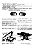
This appliance is design certified for line contact for furnaces
installed horizontally. The intersection of the furnace top and
sides form a line.
This line may be in contact with combustible material. However,
refer to "Venting" and "Clearances" in this manual for additional
information.
Secure a platform constructed of plywood or other building
material to the floor joists. Sheet metal, 12" in front of the
furnace is required. Refer to Figure 6 for details.
WARNING: When a furnace is installed in an attic or other
insulated space, keep all insulating materials at least 12"
away from furnace and burner combustion air openings.
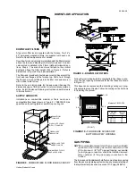
CRAWL SPACE INSTALLATION
The furnace can be hung from floor hoists or installed on suitable
blocks or pad. Blocks or pad installations shall provide adequate
height to ensure the unit will not be subject to water damage.
When suspending the furnace from rafters or floor joists using
rod, pipe or straps, refer to Physical Data (Page 4) for furnace
weights to determine suitable means of suspension. Angle
supports should be placed at the supply air end and near the
blower deck. Units may also be suspended by using straps or
other material at the same location. All four suspension points
must be level to ensure quiet furnace operation.
1/4"
SUPPORT
ROD
ANGLE IRON
BRACKET
6" MIN BETWEEN
ROD & FURNACE
MIN. 1' CLEARANCE
BETWEEN FURNACE
TOP & COMBUSTIBLES
1" MAX BETWEEN
ROD & FURNACE
1" MAX BETWEEN
ROD & FURNACE
IA
MON
80
D
D
IA
MON
80
D
D
UPFLOW/HORIZONTAL MODELS
VENT (MAINTAIN
REQUIRED CLEARANCES
TO COMBUSTIBLES)
GAS PIPING
SEDIMENT TRAP
12"
30" MIN
WORK AREA
SHEET METAL
IN FRONT
OF FURNACE
RETURN AIR
SUPPLY AIR
LINE CONTACT ONLY PERMISSIBLE
BETWEEN LINES FORMED BY THE
INTERSECTION OF FURNACE TOP
AND TWO SIDES AND BUILDING
JOISTS, STUDS OR FRAMING
FIGURE 6 - TYPICAL ATTIC INSTALLATION
FIGURE 7 - TYPICAL FURNACE INSTALLATION
USING SUSPENSION MATERIALS
HORIZONTAL APPLICATION - P2MP MODELS ONLY
2. Remove the four screws securing the front bottom angle and
remove it from the unit. Keep the angle for reinstallation.
3. Remove the screws from the furnace wrapper which secure
the bottom closure panel and remove the panel from the
blower compartment by pulling it forward and tilting upward.
4. Reinstall the front bottom angle and access doors.
Bottom return applications normally pull return air through a
base platform or return air plenum. Refer to Figure 5 for opening
dimensions. Be sure the return platform structure is suitable to
support the weight of the furnace. Seal the furnace to the
plenum to prevent air leakage.
NOTE: If an external mounted filter rack is being used, see the
instructions provided with that accessory for proper hole
cut size.
Upflow attic installations must meet all minimum clearances to
combustibles and have floor support with required service
accessibility.
650.69-N3
8
Unitary Products Group
Содержание P2DP Series
Страница 23: ...NOTES 650 69 N3 Unitary Products Group 23 ...


