


OPERATION AND MAINTENANCE
SEQUENCE OF OPERATION
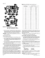
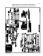
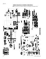
The following describes the sequence of operation of the
furnace. Refer to the schematic wiring diagram (page 19) for
component location.
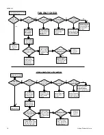
CONTINUOUS BLOWER
On cooling/heating thermostats with fan switch, when the fan
switch is set in the "ON" position, a circuit is completed between
terminals R and G of the thermostat. The blower motor is
energized through the cool fan terminal and runs on the se-
lected speed.
INTERMITTENT BLOWER - COOLING
On cooling/heating thermostats with fan switch, when the fan
switch is set in the "auto" position and the thermostat calls for
cooling, a circuit is completed between the R, Y and G termi-
nals. The motor is energized through the cool fan terminal and
runs on the selected speed. The fan off setting is fixed at 60
seconds for SEER enhancement.
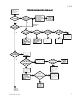
HEATING CYCLE
CAUTION: Label all wires prior to disconnecting when servic-
ing controls. Wiring errors can cause improper and dan-
gerous operation. Verify proper operation after servicing.
When the system switch is set on HEAT and the fan is set on
AUTO, and the room thermostat calls for heat, a circuit is
completed between terminals R and W of the thermostat. When
the proper amount of combustion air is being provided, a
pressure switch activates the ignition control
The ignition control provides a 31-second warm-up period. The
gas valve then opens for seven seconds.
As gas starts to flow and ignition occurs, the flame sensor
begins its sensing function. If a flame is detected within seven
seconds after ignition, normal furnace operation continues until
the thermostat circuit between R and W is opened. After flame
is present for 30 seconds, the circulating blower is energized.
When the thermostat circuit opens, the ignition control is deener-
gized. With the ignition control deenergized, the gas flow stops
and the burner flames are extinguished. The venter continues to
operate for 15 seconds after the gas flow stops.
The blower motor continues to operate for the amount of time
set by the fan-off delay dip switches located on the control
board. The heating cycle is then complete, and the unit is ready
for the start of the next heating cycle.
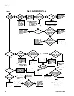
If flame is not detected within the seven second sensing period,
the gas valve is deenergized. The control is equipped with a
re-try option. This provides a 60 second wait following an
unsuccessful ignition attempt (flame not detected).
After the 60 second wait, the ignition sequence is restarted with
an additional 10 seconds of igniter warm-up time. If this ignition
attempt is unsuccessful, one more re-try will be made before
lockout.
A momentary loss of gas supply, flame blowout, or a shorted
or open condition in the flame probe circuit will be sensed within
0.8 seconds. The gas valve will deenergize and the control will
restart the ignition sequence after waiting 60 seconds. Recy-
cles will begin and the burner will operate normally if the gas
supply returns, or the fault condition is corrected prior to the
last ignition attempt. Otherwise, the control will lockout.
The control will repeat the ignition sequence for a total of four
recycles if flame is lost within the first 10 seconds of estab-
lishment.
If flame is established for more than 10 seconds after ignition,
the control will clear the ignition attempt (retry) counter. If flame
is lost after 10 seconds, it will restart the ignition sequence. This
can occur a maximum of five times.
During burner operation, a momentary loss of power of 50
milliseconds or longer will drop out the main gas valve. When
the power is restored, the gas valve will remain deenergized
and a restart of the ignition sequence will begin immediately.
Hot Surface Ignition System
WARNING: Do not attempt to light this furnace by hand (with
a match or any other means). There may be a potential
shock hazard from the components of the hot surface
ignition system. The furnace can only be lit automatically
by its hot surface ignition system.
MAINTENANCE
Air Filters
The filters should be checked periodically for dirt accumulation.
Dirty filters greatly restrict the flow of air and overburden the
system.
Clean the filters at least every three months. See the section
titled "Filters" for filter removal instructions. On new construc-
tion, check the filters every week for the first four weeks. Inspect
the filters every three weeks after that, especially if the system
is running constantly.
All filters used with the furnace are the high-velocity, cleanable
type. Clean these filters by washing in warm water. Make sure
to shake all the water out of the filter and have it reasonably
dry before installing it in the furnace. When replacing filters, be
sure to use the same size and type as originally supplied.
Lubrication
Blower motors in these furnaces are permanently lubricated
and do not require periodic oiling.
BLOWER CARE
Even with good filters properly in place, blower wheels and
motors will become dust laden after long months of operation.
The entire blower assembly should be inspected annually. If
the motor and wheel are heavily coated with dust, they can be
brushed and cleaned with a vacuum cleaner.
The procedure for removing the direct drive blower assembly
for cleaning is as follows:
1. Disconnect the electrical supply to the furnace.
2. Remove the access panels.
3. Disconnect the two wire harness plugs from the top of the
control box.
4. Remove the four screws holding the control box and
position it out of the way.
5. Remove the screws which retain blower to blower deck.
6. Remove the blower assembly with the control wiring still
attached.
7. Vacuum the motor and the blower using a soft brush
attachment. Care must be used not to disturb any balance
weights (clips) on the blower wheel vanes.
8. Before reinstalling the blower assembly, inspect the heat
exchanger which is visible in the blower opening of the
blower deck. If it requires cleaning, vacuum it with a soft
brush attachment.
650.69-N3
14
Unitary Products Group
Содержание P2DP Series
Страница 23: ...NOTES 650 69 N3 Unitary Products Group 23 ...


