DOWNFLOW FILTERS
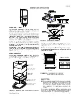
A top return filter rack is supplied with the furnace. Two 14" x
20" permanent washable filters are supplied with each unit.
Refer to Downflow Application for details.
Downflow furnaces typically are installed with the filters located
above the furnace, extending into the return air duct. An alter-
nate method is detailed in the Filters (Upflow/Horizontal) sec-
tions, Step 4. The branch duct must attach to the vertical
ductwork above the filter height (FH) in Figure 8. Refer to
dimensions in Figure 8 for proper installation.
The filter rack (provided) should be secured to the center of the
front and rear flanges at the furnace top. Drill a hole through
the front and rear duct flange into the filter rack and secure it
with a sheet metal screw.
Refer to the unit rating plate for furnace model then see the
dimensions page of this instruction for return air plenum dimen-
sions. Install the plenum following instructions under Ductwork
in this instruction.
SUPPLY AIR DUCTS
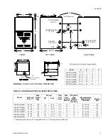
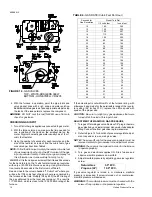
Installations on combustible material or floors must use a
combustible floor base (shown in Figure 9 - 1FB0302-304) as
specified on the rating plate or a matching cooling coil.
Follow the instructions with the combustible floor base acces-
sory. The floor opening dimensions for the floor base are shown
in Figure 10.
This base can be replaced with a matching cooling coil, prop-
erly sealed to prevent leaks. Follow the cooling coil instructions
for installing the plenum.
GAS PIPING
NOTE: An accessible manual shutoff valve must be installed
upstream of the furnace gas controls and within 6 feet
of the furnace. A 1/8" NPT plugged tapping, accessible
for test gauge connection, should be installed immedi-
ately upstream of the gas supply connection to the
furnace.
The furnace and its individual shutoff valve must be disconnected
from the gas supply piping system during any pressure testing of
that system at test pressures in excess of 1/2 psig (3.48 kPa).
A
B
1-1/8
20-5/8
28-1/2
1-1/8
CUT FLOOR
OPENING
Furnace
W idth
Cut-Out
W idth
A
16-1/4
22-1/4
26-1/4
B
14
20
24
(FRONT)
Dimensions in Inches
Models 1FB302-304
IAMON
80
D
D
FIGURE 8 - DOWNFLOW FILTERS
DOWNFLOW APPLICATION
FIGURE 10 - FLOOR BASE ACCESSORY
BOTTOM SUPPLY OPENING
FIGURE 9 - COMBUSTIBLE FLOOR BASE ACCESS’Y
DOWNFLOW
FURNACE
WARM AIR PLENUM
WITH 1" FLANGES
FIBERGLASS
INSULATION
FIBERGLASS TAPE
UNDER FLANGE
COMBUSTIBLE FLOOR
BASE ACCESSORY
650.69-N3
Unitary Products Group
9
Содержание P2DP Series
Страница 23: ...NOTES 650 69 N3 Unitary Products Group 23 ...


