FORM 160.54-M1(503)
57
YORK INTERNATIONAL
J6
10
9
8
7
6
5
4
3
2
1
N.C.
N.C.
N.C.
N.C.
N.C.
N.C.
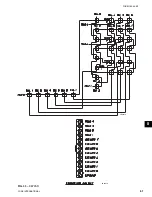
MICRO
BOARD
INVERTER
BOARD
1
2
3
4
5
N.C.
CN1
CN2
3
2
1
N.C.
RETURN
500 - 1400 VAC
BACKLIGHT
LAMP
BRIGHTNESS CONTROL (NOTE 2)
BACKLIGHT ENABLE (NOTE 1)
GND
+ 12 VDC (NOTE 3)
INVERTER CABLE 031-01770-003
DISPLAY BACKLIGHT INVERTER BOARD
TYPE: TDK CXA-L0612-VJL
PART NUMBER: 031-01789-000
FOR: SHARP LQ10D367 &
LG SEMICON LP104V2-W DISPLAYS
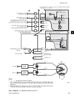
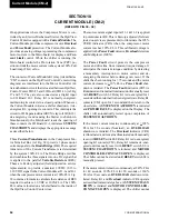
CN1-4. The lamp dimmer cir cuit var ies the voltage at
CN1-4 over the range of 0 to +3.0VDC. 0VDC pro duc es
maximum (100%) bright ness; +3.0VDC pro duc es mini-
mum (0%) bright ness. Voltages between these values
produce a linear bright ness 0 and 100%. Connector
CN2 applies the high volt age lamp il lu mi na tion signal
to the lamp.
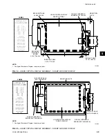
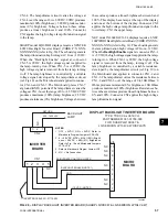
SHARP model LQ10D421 displays require a XENTEK
LS520 Backlight Inverter Board (YORK P/N XXX-
XXXXX-XXX) (refer to Fig. 30). These boards gen er ate
the lamp illumination high voltage AC from +12VDC.
When the “Backlight Enable” signal at con nec tor
CN1-5 is 0VDC, the high voltage signal is ap plied to
the lamp, turning it on. When CN1-5 is +12VDC, the
high voltage signal is re moved from the lamp, turning
it off. The lamp bright ness is controlled by a variable
voltage sig nal, de vel oped by the lamp dim mer circuit
(ref. Fig.10) on the Microboard and ap plied to connec-
tor CN1-6 and CN1-7. The Microboard plac es CN1-7
at ground (GND) po ten tial. The lamp dim mer varies the
voltage at CN1-6 over the range of 0 to +2.5VDC. 0VDC
pro duc es max i mum (100%) lamp bright ness; 2.5VDC
pro duc es min i mum (0%) bright ness. Volt ag es between
these val ues produce a linear brightness between 0 and
100%. This display has a lamp at the top of the display
and one at the bottom of the display. Connector CN2
ap plies the high voltage lamp il lu mi na tion signal to the
lower lamp; CN3 the upper lamp.
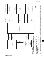
NEC model NL6448AC33-24 displays require an NEC
104PWBR1 Backlight Inverter Board (YORK P/N XXX-
XXXXX-XXX) (refer to Fig. 31). These boards gen er ate
the lamp illumination high voltage AC from +12VDC.
When the
Backlight Enable
signal at con nec tor CN3-1
is +5VDC, the high voltage signal is ap plied to the lamp,
turn ing it on. When CN3-1 is 0VDC, the high voltage
signal is re moved from the lamp, turn ing it off. The
lamp bright ness is controlled by a vari able re sis tance,
de vel oped by the lamp dimmer circuit (ref. Fig. 10) on
the Microboard and applied to con nec tor CN3-2 and
CN3-3. The lamp dim mer varies the re sis tance be tween
CN3-2 and CN3-3 over the range of 0 to 10K Ohms. 0
Ohms pro duc es minimum (0%) bright ness; 10K Ohms
pro duc es maximum (100%) bright ness. Re sis tanc es be-
tween these extremes pro duce lin ear bright ness be tween
0% and 100%. Con nec tor CN2 applies the high volt age
lamp il lu mi na tion signal.
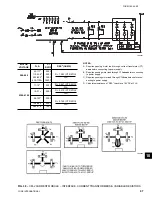
FIG. 29 –
DISPLAY BACKLIGHT INVERTER BOARD (SHARP LQ10D367 & LG SEMICON LP104V2-W)
NOTES:
1. OFF = 0VDC; ON = +5VDC. Refer to
Microboard Program Jumpers JP3 & JP4.
2. 0 - +3.0VDC. 0VDC = MAX (100%) Bright-
ness; +3.0VDC = MIN (0%) Brightness.
Refer to Fig. 10 and Microboard Jumpers
JP7 & JP8.
3. Refer to Microboard Program Jumper JP5.
4. N.C. = No Connection.
LD05528
7
Содержание MAXE OPTIVIEW YK
Страница 28: ...YORK INTERNATIONAL 28 FORM 160 54 M1 503 Microboard FIG 7 MICROBOARD LD07776...
Страница 60: ...YORK INTERNATIONAL 60 FORM 160 54 M1 503 Keypad FIG 32 KEYPAD CONNECTOR LD04074...
Страница 61: ...FORM 160 54 M1 503 61 YORK INTERNATIONAL FIG 33 KEYPAD LD04075 LD04076 8...
Страница 173: ...FORM 160 54 M1 503 173 YORK INTERNATIONAL 26 This page intentionally left blank...
Страница 177: ...FORM 160 54 M1 503 177 YORK INTERNATIONAL 26 This page intentionally left blank...

