


AYK550-UH User’s Manual
197
Serial Communication – FBA
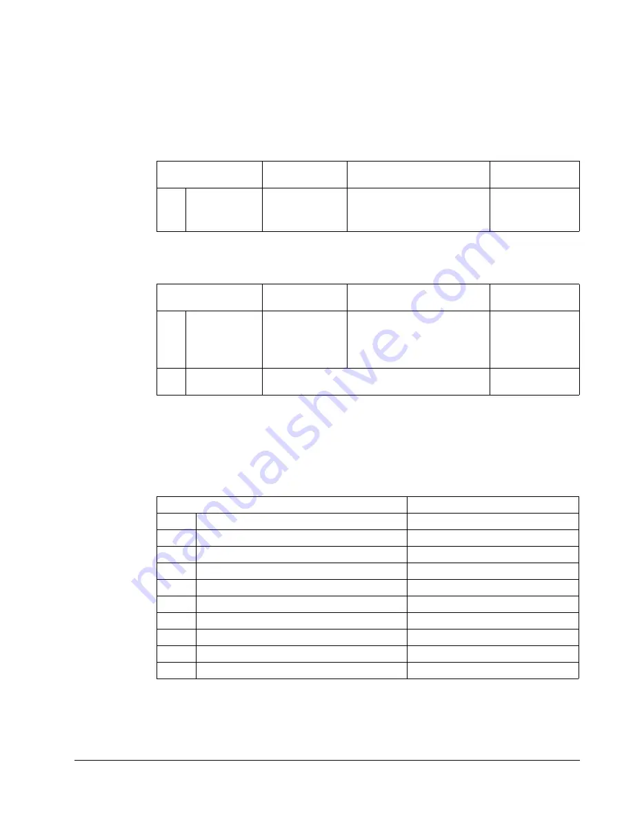
PID Control Setpoint Source
Using the fieldbus for the PID control setpoint requires:
• Drive parameter values set as defined below.
• Fieldbus controller supplied setpoint value in the appropriate location. (As defined
in "Analog Output Control" above.)
Communication Fault
When using fieldbus control, specify the drive’s action if serial communication is lost.
Feedback from the Drive – FBA
Inputs to the controller (drive outputs) have pre-defined meanings established by the
protocol. This feedback does not require drive configuration. The following table lists
a sample of feedback data. For a complete listing, see all parameters listed in
"Parameter Descriptions".
Scaling
To scale the drive parameter values see the "Actual Value Scaling" in the following
sections, as appropriate:
Drive Parameter
Value
Description
Protocol
Reference
4010
SETPOINT
SEL
8 (
COMM
VALUE
1)
9 (
COMM
+
AI
1)
10 (
COMM
*
AI
1)
Setpoint is 0135 value (plus or
times AI1)
–
Drive Parameter
Value
Description
Protocol
Reference
3018
COMM
FAULT
FUNC
0 (
NOT
SEL
)
1 (
FAULT
)
2 (
CONST
SP
7)
3 (
LAST
SPEED
)
Set for appropriate drive
response.
–
3019
COMM
FAULT
TIME
Set time delay before acting on a communication
loss.
–
Drive Parameter
Protocol Reference
0102
SPEED
0103
FREQ OUTPUT
0104
CURRENT
0105
TORQUE
0106
POWER
0107
DC BUS VOLT
0109
OUTPUT VOLTAGE
0301
FB STATUS WORD – bit 0 (STOP)
0301
FB STATUS WORD – bit 2 (REV)
0118
DI1-3 STATUS – bit 1 (DI3)
Содержание AYK 550
Страница 256: ...D1 AYK550 UH User s Manual Appendix D Appendix D Base Drive Drawing 205662 Drawings Fig 1...
Страница 257: ...AYK550 UH User s Manual D2 Appendix D Base Drive w Fused Disconnect Drawing 205648 Fig 2...
Страница 258: ...D3 AYK550 UH User s Manual Appendix D Base Drive w Non Fused Disconnect Drawing 205647 Fig 3...
Страница 259: ...AYK550 UH User s Manual D4 Appendix D Base Drive w ByPass Fused Disconnect Drawing 205651 Fig 4...
Страница 260: ...D5 AYK550 UH User s Manual Appendix D Base Drive w Bypass Non Fused Disconnect Drawing 205649 Fig 5...
Страница 261: ...AYK550 UH User s Manual D6 Appendix D Single Point Power Base Drive w ByPass Non Fused Disconnect Drawing 205653 Fig 6...
Страница 262: ...D7 AYK550 UH User s Manual Appendix D Single Point Power Base Drive w Non Fused Disconnect Drawing 205663 Fig 7...
Страница 263: ...AYK550 UH User s Manual D8 Appendix D Base Drive w ByPass Fused Disconnect Drawing 205652 Fig 8...
Страница 264: ...D9 AYK550 UH User s Manual Appendix D Base Drive w ByPass Non Fused Disconnect Drawing 205650 Fig 9...
Страница 265: ...AYK550 UH User s Manual D10 Appendix D Single Point Power Base Drive w ByPass Non Fused Disconnect Drawing 205654 Fig 10...
Страница 266: ...D11 AYK550 UH User s Manual Appendix D Base Drive w ByPass Non Fused Disconnect Drawing 206650 Fig 11...


