661693-UIM-E-1212
6
Johnson Controls Unitary Products
Please refer to Outdoor Unit Tech Guide to verify which TXV is installed
in this coil and that this is a valid system match for the AC or HP unit
installed.
The temperature sensing bulb is attached to the coil suction header
line. See Figure 11.
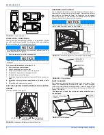
REFRIGERANT LINE CONNECTION
Connect lines as follows:
1.
Suction and liquid line connections are made outside the cabinet.
Leave the tubing connection panel attached to the cabinet with the
tubes protruding through it. Coil access panel should be removed
for brazing. The lines are swedged to receive the field line set
tubes.
2.
Remove the heat shield from the Customer Packet, soak in water,
and install over coil tubing to prevent overheating of cabinet.
3.
Wrap a water soaked rag around the coil connection tubes inside
the cabinet to avoid damaging the TXV bulb.
4.
Remove grommets where tubes exit the cabinet to prevent burning
them during brazing.
5.
Purge refrigerant lines with dry nitrogen.
6.
Braze the suction and liquid lines. Suction line must be insulated.
7.
Remove the heat shield.
8.
Re-attach the grommets to the lines carefully to prevent air leakage.
9.
Attach the coil access panel to the cabinet.
Refer to Outdoor unit Installation Manual for evacuation, leak check and
charging instructions.
Lines should be sound isolated by using appropriate hangers or strap-
ping.
All evaporator coil connections are copper-to-copper and should be
brazed with a phosphorous-copper alloy material such as Silfos-5 or
equivalent. DO NOT use soft solder.
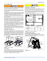
DRAIN CONNECTIONS
All drain lines should be trapped a minimum of three inches, should be
pitched away from unit drain pan and should be no smaller than the coil
drain connection.
Route the drain line so that it does not interfere with accessibility to the
coil, air handling system or filter and will not be exposed to freezing
temperatures. See Figure 2 for drain connection locations.
Coils should be installed level or pitched slightly toward the drain end.
Suggested pitch should not exceed 1/4 inch per foot of coil.
The coil is provided with a secondary drain that should be trapped and
piped to a location that will give the occupant a visual warning that the
primary drain is clogged. If the secondary drain is not used it must be
capped.
The drain pan connections are designed to ASTM Standard D 2466
Schedule 40. Use 3/4" PVC or steel threaded pipe. Since the drains are
not subject to any pressure it is not necessary to use Schedule 40 pipe
for drain lines.
FIGURE 11:
Proper Bulb Location
COIL UNDER PRESSURE.
Relieve pressure by depressing schrader core. Coil requires orifice or
TXV to be added. See outdoor unit documentation for correct orifice
or TXV to be used. Refer to unit nameplate for orifice or TXV identifi-
cation for this unit.
The coil should be open to the air for no more than 2 minutes to keep
moisture and contaminates from entering the system. If the coil can-
not be brazed into the refrigeration system in that time, the ends
should be temporarily closed or plugged. For a short term delay, use
masking tape over the ends of the copper tubing to close the tube to
the air. For a longer term delay, use plugs or caps. There is no need
to purge the coil if this procedure is followed.
Dry nitrogen should always be supplied through the tubing while it is
being brazed, because the temperature required is high enough to
cause oxidation of the copper unless an inert atmosphere is provided.
The flow of dry nitrogen should continue until the joint has cooled.
Always use a pressure regulator and safety valve to insure that only
low pressure dry nitrogen is introduced into the tubing. Only a small
flow is necessary to displace air and prevent oxidation.
Route the refrigerant lines to the coil in a manner that will not obstruct
service access to the coil, air handling system, or filter.
TXV BULB
(Cover completely
with insulation)
SCREW
CLAMP
NUT
SUCTION LINE
NOTICE
NOTICE
ALWAYS evacuate the coil and line. Set tubing to 500
microns before opening outdoor unit service valves.
Threaded drain connection should be hand-tightened, plus no more
than 1/16 turn.
When the coil is installed in an attic or above a finished ceiling, an
auxiliary drain pan should be provided under the coil if specified by
local building codes. When this exterior secondary drain pan is used
that drain should be piped to a location that will give the occupant a
visual warning that the primary drain is clogged.
NOTICE
Содержание 41HP AHR18B
Страница 1: ......


