


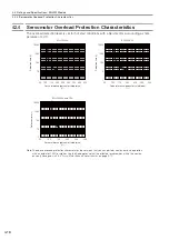


4.4 External Dimensions
4.4.1 SGLFW2-30
4-18
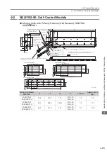
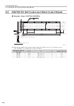
Moving Coils with Polarity Sensors (Hall Sensors): SGLFW2-30A
AS
Moving Coil Model
SGLFW2-
L1
L2
L3
L4
Approx. Mass
[kg]
30A120AS1
125
52.5
105.9
300
±
30
0.9
30A120AS1H
500
±
50
30A230AS1
230
157.5
210.9
300
±
30
1.7
30A230AS1H
500
±
50
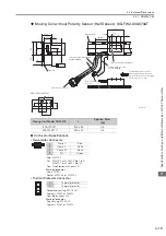
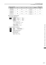
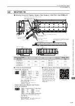
Connector Specifications
Polarity Sensor (Hall Sensor) Output Signal
•
Servomotor Connector
The figure on the right shows
the relationship between the
Su, Sv, and Sw polarity sen-
sor (hall sensor) output sig-
nals and the inverse power
of each motor phase Vu, Vv,
and Vw when the Moving
Coil moves in the direction
indicated by the arrow in the
dimensional drawings of the
Moving Coil.
Plug: 350779-1
Pins: 350218-3 or 350547-3 (No.1 to 3)
350654-1 or 350669-1 (No. 4)
From Tyco Electronics Japan G.K.
Mating Connector
Cap: 350780-1
Socket: 350536-3 or 350550-3
•
Polarity Sensor (Hall Sensor) and Thermal
Protector Connector
Pin connector: 17JE-23090-02 (D8C) -CG
From DDK Ltd.
Mating Connector
Socket connector: 17JE-13090-02 (D8C) A-CG
Studs: 17L-002C or 17L-002C1
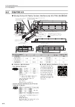
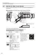
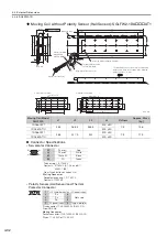
Gap 0.8
Thermal protector relay
connector (Molex Japan LLC)
Polarity sensor
(hall sensor)
Polarity sensor (hall sensor)
and thermal protector cable
UL20276, AWG28
2 × #4-40 UNC
screws
Thermal protector relay cable
UL1333, AWG22
Thermal protector cable
UL1333, AWG20
(7 dia.)
50 min.
Servomotor Main Circuit Cable
UL2586, AWG19
Refer to the following figures
and
.
The Moving Coil moves in the
direction indicated by the arrow
when current flows in the following
phase sequence: U, V, W.
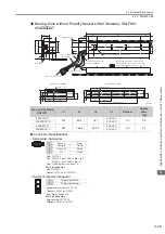
Unit: mm
Polarity sensor (hall sensor) and
thermal protector connector
Servomotor
connector
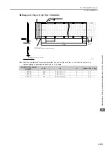
Magnetic Way
50 min.
Receptacle housing: 5557-02R
Plug housing: 5559-02P
(27.5)
(27.5)
(27.5) 1.5
(55)
(0.5)
15
50
12
(6)
29
0.1
15
26.7
L2
L3
(33.2)
L1
12.5
0.1
(10.2)
27
40
0.1
31
(7)
7.5
12.6
0.2
L4
L4
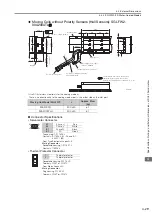
SGLFW2-30A120AS
SGLFW2-30A230AS
15
31
12
7.5
39.3
52.5
27
15
31
12
7.5
39.3
52.5
27
4 × M4 × 8
8 × M4 × 8
157.5 (52.5 × 3)
Vu
Vv
Vw
Su
Sv
Sw
0
180
360
540
Electrical angle (°)
Inverse power (V)
1
2
3
4
1
Phase U
Red
2
Phase V
White
3
Phase W
Black
4
FG
Green
9
6
5
1
1
+5 V (thermal protector), +5 V (power supply)
2
Su
6
Not used
3
Sv
7
4
Sw
8
5
0 V (power supply)
9
Thermal protector