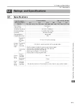


5.3 External Dimensions
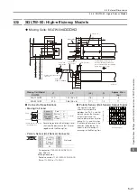
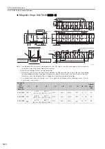
5.3.4 SGLTW-40: Standard Models
5-18
5.3.4
SGLTW-40: Standard Models
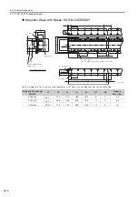
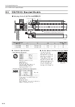
Moving Coils: SGLTW-40A
B
Moving Coil Model
SGLTW-
L1
L2
(L3)
N
Approx. Mass
[kg]
40A400B
394.2
360 (60
×
6)
(15)
14
15
40A600B
574.2
540 (60
×
9)
(15)
20
22
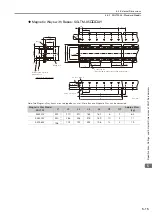
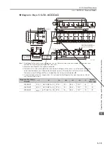
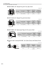
Connector Specifications
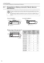
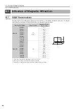
Polarity Sensor (Hall Sensor) Output Signal
•
Servomotor Connector
The figure on the right
shows the relationship
between the Su, Sv, and Sw
polarity sensor (hall sensor)
output signals and the
inverse power of each motor
phase Vu, Vv, and Vw when
the Moving Coil moves in the
direction indicated by the
arrow in the dimensional
drawings of the Moving Coil.
Receptacle: MS3102A-22-22P
From DDK Ltd.
Mating Connector
Right-angle plug: MS3108B22-22S
Straight plug: MS3106B22-22S
Cable clamp: MS3057-12A
•
Polarity Sensor (Hall Sensor) Connector
Pin connector: 17JE-23090-02 (D8C)-CG
From DDK Ltd.
Mating Connector
Socket connector: 17JE-13090-02 (D8C)A-CG
Studs: 17L-002C or 17L-002C1
Polarity sensor (hall sensor)
Receptacle
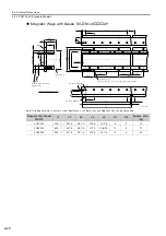
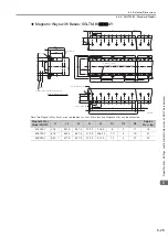
Magnetic Way
2
#4-40
UNC screws
64 min.
The Moving Coil moves in the direction indicated by the arrow
when current flows in the following phase sequence: U, V, W.
Unit: mm
(4.2 dia.)
(Gap: 1.4 without magnet cover)
(Gap: 1.2 with magnet cover)
(25.1 without magnet cover)
(25.3 with magnet cover)
500
±
50
75
(83)
78
16
(L3)
20
63
L1
L2
40
60
(19.1)
(111.8)
97
1
30
38
98
124
149.8
(19.1)
N
×
M8
×
16
Vu
Vv
Vw
Su
Sv
Sw
0
180
360
540
Inverse power (V)
Electrical angle (
°
)
A
B
D
C
A
Phase U
B
Phase V
C
Phase W
D
Ground
9
6
5
1
1
+5 V (power supply)
6
Not used
2
Phase U
7
3
Phase V
8
4
Phase W
9
5
0 V (power supply)
−
−