


3.1 Model Designations
3.1.3 Precautions on Moving Coils with Polarity Sensors (Hall Sensors)
3-4
3.1.3
Precautions on Moving Coils with Polarity Sensors
(Hall Sensors)
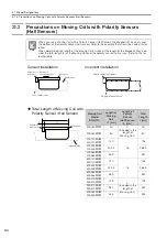
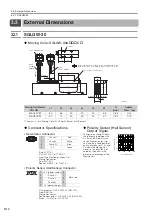
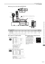
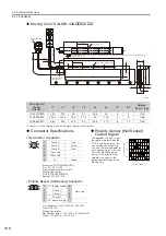
When you use a Moving Coil with a Polarity Sensor (Hall Sensor), the Magnetic Way must cover
the bottom of the polarity sensor (hall sensor). Refer to the example that shows the correct instal-
lation.
When determining the length of the Moving Coil’s stroke or the length of the Magnetic Way, con-
sider the total length (L) of the Moving Coil and the polarity sensor (hall sensor). Refer to the fol-
lowing table.
Correct Installation
Incorrect Installation
Total Length of Moving Coil with
Polarity Sensor (Hall Sensor)
Note
Polarity
s
en
s
or
(hall
s
en
s
or)
Edge of Magnetic Way
Magnetic Way
Moving Coil
Moving Coil
movement direction
Polarity
s
en
s
or (hall
s
en
s
or)
Edge of Magnetic Way
L1
A
L
Polarity
s
en
s
or
(hall
s
en
s
or)
Magnetic Way
Moving Coil
Moving Coil
Model
SGLGW-
Length of
Moving
Coil,
L1 [mm]
Length of
Polarity
Sensor
(Hall Sensor),
A [mm]
Total
Length,
L [mm]
30A050
P
50
0
(Included in the
length of
Moving Coil.)
50
30A080
P
80
80
40A140
H
40A140
P
140
16
156
40A253
H
40A253
P
252.5
268.5
40A365
H
40A365
P
365
381
60A140
H
60A140
P
140
16
156
60A253
H
60A253
P
252.5
268.5
60A365
H
60A365
P
365
381
90A200
H
90A200
P
199
0
(Included in the
length of
Moving Coil.)
199
90A370
H
90A370
P
367
367
90A535
H
90A535
P
535
535