


3.3 External Dimensions
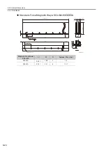
3.3.4 SGLGW-90
3
S
pecification
s
, Rating
s
, and Exter
nal Dimen
s
ion
s
of
SG
L
G
S
ervomotor
s
3-23
3.3.4
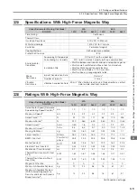
SGLGW-90
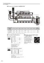
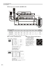
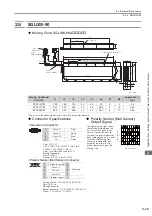
Moving Coils: SGLGW-90A
C
*
The mass is for a Moving Coil with a Polarity Sensor (Hall Sensor).
Moving Coil Model
SGLGW-
L1
L2
L3
L4
L5
L6
N1
N2
Approx. Mass
*
[kg]
90A200C
199
189
130
40
60
95
3
4
2.2
90A370C
367
357
260
40
55
285
5
8
3.65
90A535C
535
525
455
40
60
380
8
10
4.95
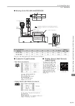
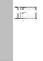
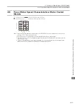
Connector Specifications
Polarity Sensor (Hall Sensor)
Output Signal
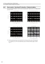
•
Servomotor Connector
The figure on the right shows
the relationship between the
Su, Sv, and Sw polarity sen-
sor (hall sensor) output sig-
nals and the inverse power of
each motor phase Vu, Vv, and
Vw when the Moving Coil
moves in the direction indi-
cated by the arrow in the
dimensional drawings of the
Moving Coil.
Plug: 350779-1
Pins: 350218-3 or 350547-3 (No.1 to 3)
350654-1 or 350669-1 (No. 4)
From Tyco Electronics Japan G.K.
Mating Connector
Cap: 350780-1
Socket: 350537-3 or 350550-3
•
Polarity Sensor (Hall Sensor) Connector
Pin connector: 17JE-23090-02 (D8C)-CG
From DDK Ltd.
Mating Connector
Socket connector: 17JE-13090-02 (D8C)A-CG
Studs: 17L-002C or 17L-002C1
UL20276, AWG26
2 × #4-40
UNC screws
The Moving Coil moves in the direction indicated by the arrow
when current flows in the following phase sequence: U, V, W.
2 × N1 × M6 × 9 (both sides)
Unit: mm
Cable
(5.3 dia.)
(10.5 dia.)
Cable
UL2517, AWG15
2
50.8
Gap1
Gap1
11.8
26
49
138
110
32
500
±
50
L2
95
8
121
500
±
50
65
L3
L4
L1
L6
L5
N2
×
M6
×
9
Vu
Vv
Vw
Su
Sv
Sw
0
180
360
540
Electrical angle (°)
Inverse power (V)
1
2
3
4
1
Phase U
Red
2
Phase V
White
3
Phase W
Blue
4
FG
Green
9
6
5
1
1
+5 V (power supply)
6
Not used
2
Phase U
7
3
Phase V
8
4
Phase W
9
5
0 V (power supply)
−
−