


5.2 Ratings and Specifications
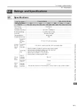
5.2.2 Ratings
5-6
5.2.2
Ratings
*1.
These values are for operation in combination with a SERVOPACK when the temperature of the armature winding is 100
°
C. The values
for other items are at 20
°
C. These are typical values.
*2.
The rated forces are the continuous allowable force values at a surrounding air temperature of 40
°
C with an aluminum heat sink of the
dimensions given in the following table.
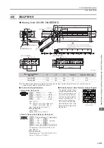
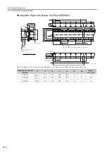
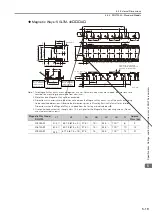
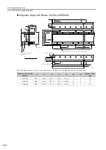
•
Heat Sink Dimensions
•
254 mm
×
254 mm
×
25 mm: SGLTW-20A170A and -35A170A
•
400 mm
×
500 mm
×
40 mm: SGLTW-20A320A, -20A460A, -35A170H, -35A320A, -35A320H, -35A460A,
and -50A170H
•
609 mm
×
762 mm
×
50 mm: SGLTW-40A400B, -40A600B, -50A320H, -80A400B, and -80A600B
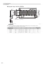
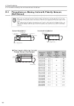
*3.
The unbalanced magnetic gap that results from the Moving Coil installation condition causes a magnetic attraction on the Moving Coil.
*4.
The value that is given is the magnetic attraction that is generated on one side of the Magnetic Way.
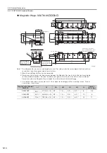
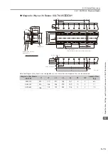
Linear Servomotor Moving
Coil Model SGLTW-
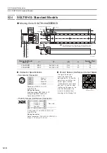
Standard Models
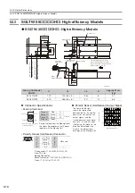
High-efficiency
Models
20A
35A
40A
80A
35A
50A
170A
320A
460A
170A
320A
460A
400B 600B
400B
600B 170H 320H 170H 320H
Rated Motor Speed
(Reference Speed during
Speed Control)
*1
3.0
3.0
3.0
2.5
2.5
2.5
1.5
2.0
2.0
2.0
2.5
2.0
2.0
2.0
Maximum
Speed
*1
m/s
5.0
5.0
5.0
5.0
5.0
5.0
3.1
3.1
2.5
2.5
4.8
4.8
3.2
3.1
Rated Force
*1, *2
N
130
250
380
220
440
670
670
1000
1300
2000
300
600
450
900
Maximum Force
*1
N
380
760
1140
660
1320
2000
2600
4000
5000
7500
600
1200
900
1800
Rated Current
*1
Arms
2.3
4.4
6.7
3.5
7.0
10.7
7.3
10.9
11.1
17.1
5.1
10.1
5.1
10.2
Maximum
Current
*1
Arms
7.7
15.4
23.2
12.1
24.2
36.7
39.4
60.6
57.9
86.9
11.9
23.9
11.8
23.6
Moving Coil Mass
kg
2.5
4.6
6.7
3.7
6.8
10
15
23
24
35
4.9
8.8
6.0
11
Force Constant
N/Arms
61.0
61.0
61.0
67.5
67.5
67.5
99.1
99.1
126
126
64.0
64.0
95.2
95.2
BEMF Constant
Vrms/
(m/s)/
phase
20.3
20.3
20.3
22.5
22.5
22.5
33.0
33.0
42.0
42.0
21.3
21.3
31.7
31.7
Motor Constant
N/
18.7
26.5
32.3
26.7
37.5
46.4
61.4
75.2
94.7
116
37.4
52.9
48.6
68.7
Electrical Time
Constant
ms
5.9
5.9
5.9
6.9
6.8
6.9
15
15
17
17
15
16
16
17
Mechanical Time
Constant
ms
7.1
6.6
6.4
5.2
4.8
4.6
4.0
4.1
2.7
2.6
3.5
3.1
2.5
2.4
Thermal
Resistance
(with Heat Sink)
K/W
1.01
0.49
0.38
0.76
0.44
0.32
0.24
0.20
0.22
0.18
0.76
0.40
0.61
0.30
Thermal
Resistance
(without Heat
Sink)
K/W
1.82
1.11
0.74
1.26
0.95
0.61
0.57
0.40
0.47
0.33
1.26
0.83
0.97
0.80
Magnetic Attrac-
tion
*3
N
0
0
0
0
0
0
0
0
0
0
0
0
0
0
Magnetic
Attraction on
One Side
*4
N
800
1590
2380
1400
2780
4170
3950
5890
7650
11400
1400
2780
2000
3980
Maximum Allow-
able Payload
kg
25
50
76
44
88
130
280
440
690
1000
33
67
92
190
Maximum Allow-
able Payload
(With External
Regenerative
Resistor and
External Dynamic
Brake Resistor)
kg
25
50
76
44
88
130
280
440
690
1000
40
82
95
190
Combined Magnetic Way,
SGLTM-
20
A
35
A
40
A
80
A
35
H
50
H
Combined Serial Converter
Unit, JZDP-
-
011
012
013
014
015
016
185
186
187
188
105
106
108
109
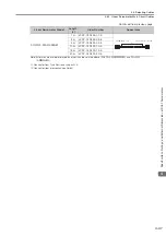
Applicable
SERVOPACKs
SGD7S-
3R8A
7R6A
120A
5R5A
120A
180A
330A
550A
5R5A
120A
5R5A
120A
SGD7W-
SGD7C-
5R5A
7R6A
−
5R5A
−
5R5A
−
5R5A
−
W