3 Wiring and Connection
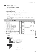
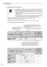
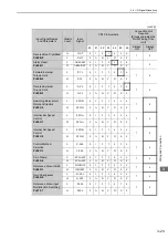
3.4.1 Input Signal Allocations
3-24
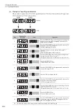
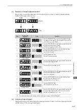
(3) Example of Input Signal Allocation
The procedure to replace Servo ON (/S-ON) signal allocated on CN1-40 and Forward External Torque Limit
(/P-CL) allocated on CN1-45 is shown below.
Pn50A
Pn50B
Before
After
Step
Display after
Operation
Keys
Operation
1
Press the MODE/SET Key to select the parameter setting. If a
parameter other than Pn50A is displayed, press the UP or
DOWN Key to set Pn50A.
2
Press the DATA/SHIFT Key for approximately one second to
display the current data of Pn50A.
(/S-ON is allocated on CN1-40.)
3
Press the UP key to set to the value on the far right "1"
(Pn50A.0 = 1).
(Sequence input signals can be freely set.)
4
Press the DATA/SHIFT Key to select the second digit from
the right. Press the UP key to set to "5."
(Changes the allocation of /S-ON from CN1-40 to CN1-45.)
5
Display flashes.
Press the MODE/SET Key.
The data flashes and is saved.
6
Press the DATA/SHIFT Key for approximately one second to
return to the display Pn50A.
7
Press the UP key to display Pn50B.
8
Press the DATA/SHIFT Key for approximately one second to
display the current data of Pn50B.
(/P-CL is allocated on CN1-45.)
9
Press the DATA/SHIFT Key to select the third digit from the
right. Press the UP Key to set "0."
(Changes the allocation of /P-CL from CN1-45 to CN1-40.)
10
Display flashes.
Press the MODE/SET Key.
The value flashes and is saved.
11
Press the DATA/SHIFT Key for approximately one second to
return to the display Pn50B. /S-ON is mapped on CN1-45,
and /P-CL is mapped on CN1-40.
12
To enable the change in the setting, turn the control power supply OFF and ON again.
MODE/SET
DATA/
MODE/SET
DATA/
MODE/SET
DATA/
MODE/SET
DATA/
MODE/SET
DATA/
MODE/SET
DATA/
MODE/SET
DATA/
MODE/SET
DATA/
MODE/SET
DATA/
MODE/SET
DATA/
MODE/SET
DATA/

