


8.5 Monitoring Output Signals
8-7
8
Monitor Displays
(Un
)
8.5
Monitoring Output Signals
The status of output signals can be checked with the output signal monitor (Un006). The procedure for dis-
playing the status, the method of interpreting the display, and a display example are shown below.
8.5.1
Displaying Output Signal Status
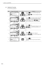
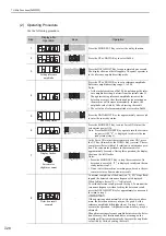
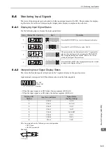
Use the following steps to display the output signal status.
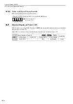
8.5.2
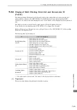
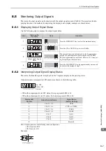
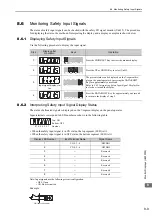
Interpreting Output Signal Display Status
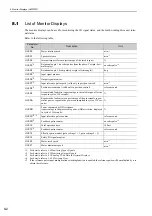
The status of allocated signals is displayed on the 7-segment display on the panel operator.
Output terminals correspond to LED numbers as shown in the following table.
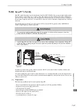
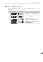
• When the output signal is in OFF status, the top segment (LED) is lit.
• When the output signal is in ON status, the bottom segment (LED) is lit.
Note: Output signals use the following circuit configuration.
• OFF: Transistor OFF
• ON: Transistor ON
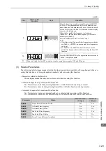
Example
Step
Display after
Operation
Keys
Operation
1
Press the MODE/SET Key to select the monitor display.
2
Press the UP or DOWN Key to select Un006.
3
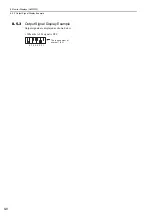
Output signal display
status
The present status can be displayed on the 7-segment dis-
play on the panel operator by pressing the DATA/SHIFT
Key for approximately one second. Refer to
8.5.2 Interpret-
ing Output Signal Display Status
.
4
Press the DATA/SHIFT Key for approximately one second
to return to the display of step 2.
MODE/SET
DATA/
MODE/SET
DATA/
MODE/SET
DATA/
MODE/SET
DATA/
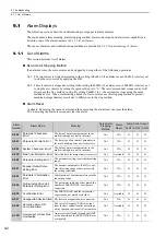
Display LED
Number
Output Terminal Name
Signal Name
(Factory Setting)
1
CN1-31
,
-32
ALM
2
CN1-25, -26
/COIN or /V-CMP
3
CN1-27,
-
28
/TGON
4
CN1-29, -30
/S-RDY
5
CN1-37
ALO1
6
CN1-38
ALO2
7
CN1-39
ALO3
8
−
Reserved
4 3 2 1
Top: OFF
Bottom: ON
Number
6
7
8
5
Analog
ON: Transistor ON