5.4 Position Control
5-33
5
Op
er
at
io
n
(4) Electrical Specifications for Pulse Train Reference
Forms of pulse train references are as shown below.
∗
Each multiplier’s maximum reference frequency before multiplication is 1 Mpps.
×
1 input pulse multiplier: 1 Mpps
×
2 input pulse multiplier: 1 Mpps
×
4 input pulse multiplier: 1 Mpps
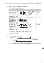
(5) I/O Signal Timing Example
I/O signal timing example is as shown below.
Note: The interval from the time the servo ON signal is turned ON until a reference pulse is input (t3) must be at least 174
ms. Otherwise the reference pulse may not be received by the multi-winding drive unit.
Pulse Train Reference Form
Electrical Specifications
Remarks
Sign + pulse train input
(SIGN + PULS signal)
Maximum reference fre-
quency: 4 Mpps
(Maximum reference fre-
quency in case of open-
collector output: 200 kpps)
t1, t2, t3, t7
≤
0.025
μ
s
t4, t5, t6
≥
0.5
μ
s
τ
≥
0.125
μ
s
T-
τ
≥
0.125
μ
s
Sign (SIGN)
H = Forward
reference
L = Reverse
reference
CW + CCW pulse train
Maximum reference fre-
quency: 4 Mpps
(Maximum reference fre-
quency in case of open-
collector output: 200 kpps)
t1, t2
≤
0.025
μ
s
t3
≥
0.5
μ
s
τ
≥
0.125
μ
s
T-
τ
≥
0.125
μ
s
−
Two-phase pulse train with
90
°
phase differential
(phase A + phase B)
Maximum reference fre-
quency: 1 Mpps*
(Maximum reference fre-
quency in case of open-
collector output: 200 kpps)
t1
≤
0.1
μ
s
t2
≤
0.1
μ
s
τ
≥
0.5
μ
s
T-
τ
≥
0.5
μ
s
Reference pulse
form is set with
Pn200.0.
Forward reference
Reverse reference
t1 t2
t3
t4
t5
t6
t7
T
SIGN
PULS
t2
t3
T
CW
CCW
t1
Forward reference
Reverse reference
Phase B leads
phase A by 90
°
.
Phase B lags
phase A by 90
°
.
Phase A
Phase B
t2
T
t1
Forward reference
Reverse reference
Servo ON
Baseblock
Sign + pulse train
Release
t1
≤
170 ms
t2
≤
6 ms
(When Pn506 is set to 0.)
t3
≥
174 ms
CN1-11
CN1-7
L
H
H
ON
t3
t2
t1

