50
YASKAWA ELECTRIC
TOEP C710656 10B YASKAWA Power Regenerative Unit - R1000 Instruction Manual
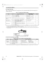
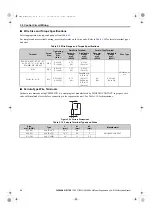
3.9 Control Circuit Wiring
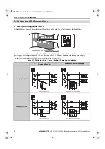
3.9 Control Circuit Wiring
NOTICE:
Do not connect AC control circuit ground to regenerative unit enclosure. Improper regenerative unit grounding can cause
control circuit malfunction.
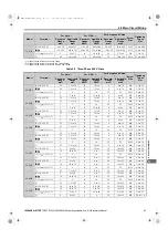
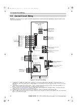
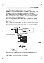
Figure 3.18
Figure 3.20 Control Circuit Wiring
<1> Set jumper S3 to change the sequence input signals (S1 to S8) between sinking and sourcing inputs. The default setting is for
Sinking Mode. Control is possible with no-voltage contacts or NPN transistors. For details, refer to
<2> The maximum output current capacity for the +V and -V terminals on the control circuit is 20 mA. Never short terV, -V,
and AC, as it can cause erroneous operation or damage the regenerative unit.
<3> Set DIP switch S1 to select between a voltage or current input signal to terminal A2. The default setting is for current input. For
details, refer to
Terminal A2 Input Signal Selection on page 57
.
<4> Set DIP switch S2 to the ON position to enable the termination resistor in a MEMOBUS/Modbus network.
<5> Monitor outputs work with devices such as analog frequency meters, ammeters, voltmeters, and wattmeters. They are not intended
for use as a feedback-type signal.
S1
S2
S3
S4
S5
S6
S7
S8
SC
E(G)
MA
MB
MC
Forced operation
command
External fault
Fault reset
(Reserved)
(Reserved)
(Reserved)
External
Baseblock
Shield ground terminal
Automatic operation
command
M1
M2
Regenerative Unit
R1000
Multi-function
digital inputs
(default setting)
Fault relay output
250 Vac, max. 1 A
30 Vdc, max 1 A
(min. 5 Vdc, 10 mA)
+V
A1
A2
A3
AC
(Reserved)
(Reserved)
(Reserved)
+24V
Control
Circuit
-V
Power supply, -10.5 Vdc,
max. 20 mA
Analog Input 1
Analog Input 2
Analog Input 3
DIP Switch S1
V
I
Termination resistor
(
120Ω
,
1/2W
)
DIP
Switch S2
Multi-function photocoupler output 1
(Operation Ready)
48 Vdc, max 50 mA
Multi-function photocoupler output 2
(During Run 1)
48 Vdc, max 50 mA
Multi-function relay
output (During MC on)
250 Vac, max. 1 A
30 Vdc, max 1 A
(min. 5 Vdc, 10 mA)
FM
AM
AC
0V
FM
AM
E(G)
Multi-function analog output 1
(Power Supply Side Power)
0 to +10 Vdc
Multi-function analog output 2
(Power Supply Current)
0 to +10 Vdc
CN5-A
CN5-B
CN5-C
Option card
connectors
Sink
Jumper S3
H1, H2
Sink/Source Sel.
Power 10.5 Vdc,
max. 20 mA
MEMOBUS/
Modbus Communication
RS-422/RS-485
max. 115.2 kbps
R+
R-
S+
S-
IG
<5>
<5>
<3>
<2>
<2>
<1>
<4>
PC
P2
P1
+
-
+
-
shielded line
main circuit terminal
twisted-pair shielded line
control circuit terminal
YEC
TOEP_C710656_10B_1_0.book 50 ページ 2015年1月8日 木曜日 午後8時55分

