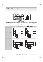
3.10 Control I/O Connections
YASKAWA ELECTRIC
TOEP C710656 10B YASKAWA Power Regenerative Unit - R1000 Instruction Manual
57
El
ect
ri
c
al
In
st
al
la
ti
o
n
3
◆
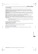
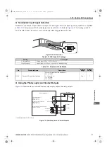
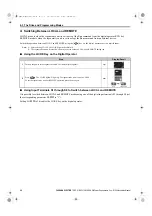
Terminal A2 Input Signal Selection
Terminal A2 can be used to input either a voltage or a current signal. Select the signal type using switch S1 as explained
in
. Set parameter H3-09 accordingly as shown in
. Refer to
for locating switch S1.
To set the DIP switch, use tweezers or a tool with a tip width of approximately 0.8 mm.
Figure 3.1
Figure 3.29 DIP Switch S1
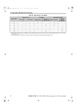
Table 3.12 DIP Switch S1 Settings
Table 3.13 Parameter H3-09 Details
◆
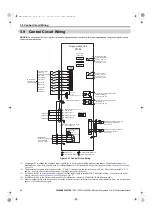
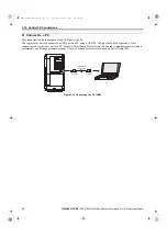
Using the Photocoupler and Contact Outputs
illustrates the use of multi-function relay outputs and the fault relay outputs.
Figure 3.2
Figure 3.30 Photocoupler and Contact Outputs
Setting
Description
V (left position)
Voltage input (-10 to +10 V or 0 to 10 V)
I (right position)
Current input (4 to 20 mA or 0 to 20 mA): default setting
No.
Parameter Name
Description
Setting
Range
Default
Setting
H3-09
Terminal A2 signal level selection
Selects the signal level for terminal A2.
0: 0 to 10 Vdc
1: -10 to 10 Vdc
2: 4 to 20 mA
3: 0 to 20 mA
0 to 3
2
<1> Minimum load: 5 Vdc, 10 mA
DIP switch S1
V
I
MA
M1
M2
MB
MC
P1
P2
PC
Relay
SA
SA
Max
250 Vac
Relay
Relay
Relay
Max 48 Vdc
Max 48 Vdc
Controller
Multi-function relay output
<1>
250 Vac, max. 1 A
30 Vdc, max. 1 A
Fault relay output
<1>
250 Vac, max. 1 A
30 Vdc, max. 1 A
Through mode
Fault
Multi-Function Photocoupler Output
48 Vdc 0 to 50 mA
Through mode
Through mode
Regenerative Unit
YEC
TOEP_C710656_10B_1_0.book 57 ページ 2015年1月8日 木曜日 午後8時55分

