


B.2 Parameter Tables
158
YASKAWA ELECTRIC
TOEP C710656 10B YASKAWA Power Regenerative Unit - R1000 Instruction Manual
U1-11
(4AH)
Output Terminal
Status
Output
Term Sts
Displays the output terminal status.
No signal
output
available
–
U1-12
(4BH)
Drive Status
Int Ctl Sts 1
Verifies the regenerative unit operation status.
No signal
output
available
–
U1-13
(4EH)
Terminal A1 Input
Level
Term A1
Level
Displays the signal level to analog input terminal A1.
10 V: 100%
0.1%
U1-14
(4FH)
Terminal A2 Input
Level
Term A2
Level
Displays the signal level to analog input terminal A2.
10 V: 100%
0.1%
U1-15
(50H)
Terminal A3 Input
Level
Term A3
Level
Displays the signal level to analog input terminal A3.
10 V: 100%
0.1%
U1-18
(61H)
oPE Fault
Parameter
OPE Error
Code
Displays the parameter number that caused the oPE02 or oPE08 operation
error.
No signal
output
available
–
U1-19
(66H)
MEMOBUS/
Modbus Error
Code
Transmit
Err
Displays the contents of a MEMOBUS/Modbus error.
No signal
output
available
–
U1-25
(4DH)
Software Number
(Flash)
CPU 1 SW
Number
FLASH ID
No signal
output
available
–
U1-26
(5BH)
Software No.
(ROM)
CPU 2 SW
Number
ROM ID
No signal
output
available
–
U1-27
(7A8H)
Message ID
(OPR)
MessageID
(OPR)
Shows the message ID number for OPE.
No signal
output
available
–
U1-28
(7A9H)
Message ID
(INV)
MessageID
(INV)
Shows the message ID number for INV.
No signal
output
available
–
U1-52
(1081H)
DC Bus Voltage
Feedback
DC V
Feedback
Shows the DC bus voltage feedback value.
200 V Class
10 V: 400 V
400 V Class
10 V: 800 V
1 V
No.
(Address
Hex)
Name
LCD
Display
Description
Analog
Output
Level
Unit
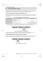
U1 - 11=
0 0 0 0 0 0 0 0
Multi-Function Relay Output
(terminal M1-M2)
Multi-Function Photocoupler Output
(terminal P1-PC)
Multi-Function Photocoupler Output
(terminal P2-PC)
Reserved
Fault Relay
(terminal MA/MB-MC closed
MA/MB-MC open)
1: ON 0: OFF
YEC
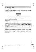
U1 - 12=
0 0 0 0 0 0 0 0
Bit 0: During RUN
Bit 1: Reserved
Bit 2: Reserved
Bit 3: Fault reset signal input
Bit 4: Power supply established
(0: Not completed, 1: Completed)
Bit 5: Operation ready
Bit 6: Minor fault detected
Bit 7: Fault detected
CRC Error
Data Length Error
Not Used
Parity Error
Overrun Error
Framing Error
Timed Out
Not Used
: ON
: OFF
YEC
TOEP_C710656_10B_1_0.book 158 ページ 2015年1月8日 木曜日 午後8時55分


