


10
-36
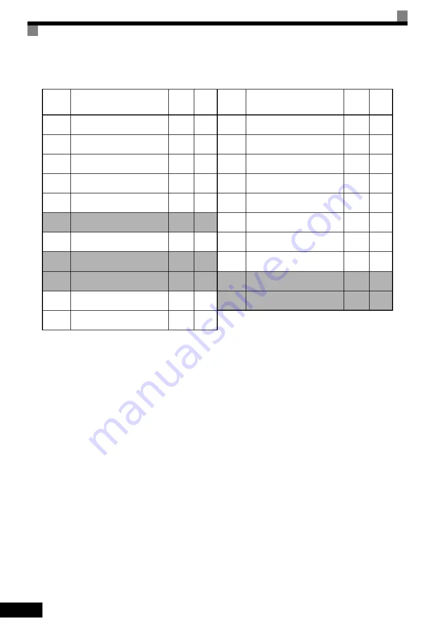
Table 10.7 User Constants (Continued)
* 1. Not initialized. (Japanese standard specifications: A1-01 = 1, A1-02 = 2)
* 2. The factory setting will change when the control method is changed. The V/f control factory settings are given.
* 3. The factory setting is 1.0 when using flux vector control.
* 4. The factory setting is 2.00 s when Inverter capacity is 55 kW min.
The factory setting will change if the control method is changed. The open-loop vector factory setting is given.
* 5. By setting E2-11 (Motor rated output) the appropriate value will be set.
* 6. The factory setting depends on the Inverter capacity. The values for a 200 V Class Inverter for 0.4 kW are given.
* 7. The factory setting will change when the control method is changed. The flux vector control factory settings are given.
* 8. Only 1 (VT) can be set for 200 V Class 110 kW as well as 400 V Class 220 kW and 300 kW Inverters.
* 9. Setting for 200 V Class Inverters. For 400 V Class Inverters, double the value.
* 10.E1-11 and E1-12 are disregarded when set to 0.0.
* 11.E1-13 is set to the same value as E1-05 by autotuning.
* 12.The values in parentheses indicate factory settings when initialized in 3-wire sequence.
* 13.If the setting is 0, the axis will accelerate to the specified speed over the specified acceleration time (C1-01 to C1-08).
* 14.C6-01 = 1:120%, C6-01 = 0:150%
* 15.This constant can be monitored or set only when F is set for C6-02.
* 16.Applicable for F7-Series Inverters with software versions PRG:1031 or later.
* 17.Refer to
MECHATROLINK COMMUNICATIONS INTERFACE CARD INSTRUCTIONS (TOBPC73060008)
for details.
* 18.Applicable for F7-series Inverters with software versions PRG: 1032 or latter.
* 19.Applicable for F7-series Inverters with software versions PRG: 1033 or latter.
o2-04
kVA selection
0
*6
o2-05
Frequency reference setting
method selection
0
o2-06
Operation selection when digital
operator is disconnected
0
o2-07
Cumulative operation time setting
0
o2-08
Cumulative operation time selec-
tion
0
o2-09
*19
For factory adjustment
0
o2-10
Fan operation time setting
0
o2-12
Fault trace/fault history clear func-
tion
0
o2-14
Output power monitor clear selec-
tion
0
o3-01
Copy function selection
0
o3-02
Read permitted selection
0
No.
Name
Fac-
tory
Setting
Set-
ting
T1-00
Motor 1/2 selection
1
T1-01
Autotuning mode selection
2
*2
T1-02
Motor output power
0.40
*6
T1-03
Motor rated voltage
200.0
*9
T1-04
Motor rated current
1.90
*6
T1-05
Motor base frequency
60.0
T1-06
Number of motor poles
4
T1-07
Motor base speed
1750
T1-08
Number of PG pulses when turn-
ing
600
T1-09
Motor no-load current
1.20
*6
No.
Name
Fac-
tory
Setting
Set-
ting


