


3 Electrical Installation
YASKAWA Europe
TOEP_C710606_97A - AC Drive A1000 IP54READY - Quick Start Guide
EN 15
Ground Connection
Take the following precautions when grounding the drive.
• Never share the ground wire with other devices such as welding machines, etc.
• Always use a ground wire, that complies with electrical equipment technical standards. Keep ground wires as short as
possible. Leakage current is caused by the drive. Therefore, if the distance between the ground electrode and the
ground terminal is too long, potential on the ground terminal of the drive will become unstable.
• When using more than one drive, do not loop the ground wire.
Control Circuit Wiring Precautions
Consider the following precautions for wiring the control circuits.
• Separate control circuit wiring from main circuit wiring and other high-power lines.
• Separate wiring for control circuit terminals M1-M2, M3-M4, M5-M6, MA, MB, MC (contact output) from wiring to
other control circuit terminals.
• For external control power supply use a UL Listed Class 2 power supply.
• Use twisted-pair or shielded twisted-pair cables for control circuits to prevent operating faults.
• Ground the cable shields with the maximum contact area of the shield and ground.
• Cable shields should be grounded on both cable ends.
• If flexible wires with ferrules are connected they might fit tightly into the terminals. To disconnect them, grasp the wire
end with a pair of pliers, release the terminal using a straight-edge screw driver, turn the wire for about 45
°,
and pull it
gently out of the terminal. For details, refer to the Technical Manual. Use this procedure for removing the wire link
between HC, H1 and H2 when the Safe Disable function is utilized.
Main Circuit Terminals
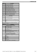
Control Circuit Terminals
The figure below shows the control circuit terminal arrangement. The drive is equipped with screwless terminals.
There are three DIP switches and two jumpers, S1 to S5, located on the terminal board.
Terminal
Type
Function
Model CIMR-A
4A0044
4A0058 to 4A0072
4A0088 to 4A0165
L1/L2/L3
Main circuit power supply input
Connects line power to the
drive
U/T1
,
V/T2
,
W/T3
Drive output
Connects to the motor
B1, B2
Braking resistor
not available
Available for connecting a
braking resistor or a braking
resistor unit option
+2
• DC reactor connection
(+1, +2) (remove the
shorting bar between
+1 and +2)
• DC power supply input
(+1,
−
)
not available
For connection
• of the drive to a DC power
supply
• of braking options
• connection of a DC reactor
+1, –
• DC power supply input
(+1,
−
)
• DC power supply input
(+1,
−
)
• Braking transistor
connection (+3,
−
)
+3
not available
−
Grounding terminal
MA MB MC
M1 M2 M5
M3 M6 M4
E(G) HC H1 H2 DM+ DM- IG R+ R- S+ S-
S1 S2 S3 S4 S5 S6 S7 S8 SN SC SP
V+ AC V- A1 A2 A3 FM AM AC MP RP AC
Use a straight-edge screwdriver
with a blade width of max 2.5 mm
and a thickness of max 0.6 mm to
release the terminals
S2
S3
S1
S4
S5