


3 Electrical Installation
EN 14
YASKAWA Europe TOEP_C710606_97A - AC Drive A1000 IP54READY - Quick Start Guide
Main and Control Circuit Wiring
Wiring the Main Circuit Input
Consider the following precautions for the main circuit input.
• Use fuses recommended in
only.
• If using a ground fault circuit breaker, make sure that it can detect both DC and high frequency current.
• If using an input switch, make sure that this switch is not operated more than once every 30 minutes.
• Use insulation caps when wiring the drive with crimp terminals. Take particular care to ensure that wiring does not
touch neighboring terminals or the surrounding case.
• Use a DC reactor or AC reactor on the input side of the drive:
–To suppress harmonic current.
–To improve the power factor on the power supply side.
–When using an advancing capacitor switch.
–With a large capacity power supply transformer (over 600 kVA).
Wiring the Main Circuit Output
Consider the following precautions for the output circuit wiring.
• Do not connect any other load than a 3 phase motor to the drives output.
• Never connect a power source to the drives output.
• Never short or ground the output terminals.
• Do not use phase correction capacitors.
• If using a contactor between the drive and motor, it should never be operated when the drive is outputting a voltage.
Operating while there is voltage output can cause large peak currents, thus tripping the over current detection or
damage the drive.
L3
L3 L2
L2 L1
L1
L3 L2 L1
E
L3
L2
L1
PE
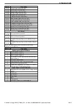
Make sure the ground wire is grounded
Enclosure panel
Metal plate
Grounding surface
(remove any paint or sealant)
Drive (mounted through panel cut out)
Grounding surface
(remove any paint or sealant)
Motor cable (braided shield cable, max. 10 m)
Cable clamp
Ground plate
(scrape off any visible paint)
EMC noise filter
Motor
Ground the cable shield
M6 stud for EMC grounding.
Connect to metal plate with
braided grounding strap.