


3 Electrical Installation
YASKAWA Europe
TOEP_C710606_97A - AC Drive A1000 IP54READY - Quick Start Guide
EN 13
Wiring Specification
Main Circuit
Use the fuses and line filters listed in the table below when wiring the main circuit. Make sure not to exceed the given
tightening torque values.
Tightening Torque Values
Tighten the main circuit terminals using the torque values provided by the table below.
Control Circuit
The control terminal board is equipped with screwless terminals. Always use wires within the specification listed below.
For safe wiring it is recommended to use solid wires or flexible wires with ferrules. The stripping length respectively
ferrule length should be 8 mm.
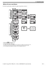
EMC Filter Installation
This drive has been tested in accordance with European standards EN61800-3. In order to comply to the EMC standards,
wire the main circuit as described below.
1. Install an appropriate EMC noise filter to the input side. See the table in
Technical Manual for details.
2. Place the drive and EMC noise filter in the same enclosure.
3. Use braided shield cable for the drive and motor wiring.
4. Remove any paint or dirt from ground connections for minimal ground impedance.
5. Prepare braided ground strap with ring terminal to ensure proper EMC grounding from the drive to the panel.
6. Use M6 stud on drives mounting frame to connect with braided ground strap to metal mounting plate of the panel.
7. Keep this EMC grounding braided strap as short as possible.
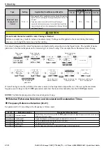
Model
CIMR-A
EMC Filter
[Block]
Main Fuse
[Bussmann]
Recom.
Motor cable
(mm
2
)
Main Circuit Terminal Sizes
R/L1,S/L2,T/L3,
U/T1,V/T2,W/T3,
– , +1, +2
+3
B1, B2
4A0044
FB-40060A
FWH-250A
16
M6
–
M5
M8
4A0058
M8
M8
4A0072
FB-40072A
25
4A0088
FB-40105A
M10
–
4A0103
35
4A0139
FB-40170A
FWH-350A
50
M10
M10
4A0165
FWH-400A
70
Terminal Size
M5
M6
M8
M10
Tightening Torque (N
m)
2.0 to 2.5
4.0 to 6.0
9.0 to 11.0
18.0 to 23.0
Wire Type
Wire size (mm
2
)
Solid
0.2 to 1.5
Flexible
0.2 to 1.0
Flexible with ferrule
0.25 to 0.5