10 ELECTRIC EQUIPMENT
10 ELECTRIC EQUIPMENT
EF494T TM 06/2011 edition
205
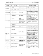
Location
No.
Parts name
Name and number of
Parts catalogue
Operation and remarks
Engine front
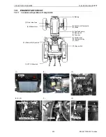
1 Battery
Battery 75D26R
1A7781-51500
Supplies power to the circuits.
2 Slow blow fuse (main)
Fuse 60A slow blow
1A6380-52700
Protects wiring & electric equipment
related to engine start.
Engine left side
3
Starter motor
(12V-1.2KW)
Starter assy.
129407-77010
Cranks the engine when the key switch
is set to the "ST" position, the range
shift to the "N", and the PTO to the "N"
status.
Engine right side
4
Fuel shut off
solenoid
Stop solenoid
119653-77950
Cuts off the fuel to the fuel injection
pump to stop the engine when the key
switch is turned off.
5 Diode
Diode
1A8160-51130
Provides protection to the wiring and
electric equipment against surge
current that occurs when the fuel shut-
off solenoid is activated.
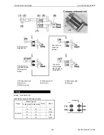
6 Fuel feed pump
Fuel feed pump assy.
1A7781-52100
Supplies the fuel to the fuel injection
pump.
7 Body earth
8 Fuse 5A
Fuse
198535-52110
Fuse for Fuel feed pump, Stop solenoid
and Neutral switches.
Inside of front
Column
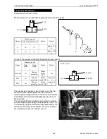
9 Start relay
Starter relay
1A7870-52950
It is activated when the range shift lever
& PTO lever are set to the "N" position.
It gives requisites for application of 12
V to the terminal S of the starter motor.
10 Solenoid relay
It is activated when the range shift lever
& PTO lever are set to the "N" position.
It gives requisites for application of 12
V to the fuel shut off solenoid.
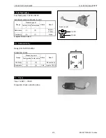
11 Timer
Timer
129211-77920
It is activated when the range shift lever
& PTO lever are set to the "N" position.
It gives requisites for application of
electric power for 1 second to the pull
coil of fuel shut off solenoid.
Front column
12 Key switch
Starter switch CMP
198162-52110
Used for ON/OFF of the battery power
to the circuits.
Transmission
case upper side
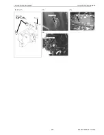
13 Main shift (N) switch
Safety starter switch
194464-52190
To start engine, main shift must be at
"N" position together with PTO shift at
“N” position.
Transmission
case rear side
14 PTO (N) switch
To start engine, PTO shift must be at
"N" position together with main shift at
“N” position.
Содержание EF-494T
Страница 1: ...EF494T TM 06 2011 edition ...
Страница 30: ...1 PERIODICAL INSPECTION 1 PERIODICAL INSPECTION EF494T TM 06 2011 edition 22 1 PERIODICAL INSPECTION ...
Страница 85: ...3 ENGINE 3 ENGINE EF494T TM 06 2011 edition 77 3 ENGINE ...
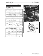
Страница 86: ...3 ENGINE 3 ENGINE EF494T TM 06 2011 edition 78 3 1 FUEL SYSTEM 3 1 1 Flow of fuel and layout of components ...
Страница 88: ...3 ENGINE 3 ENGINE EF494T TM 06 2011 edition 80 B Return ...
Страница 126: ...4 CLUTCH 4 CLUTCH EF494T TM 06 2011 edition 118 4 CLUTCH ...
Страница 130: ...4 CLUTCH 4 CLUTCH EF494T TM 06 2011 edition 122 ...
Страница 133: ...5 TRANSMISSION 5 TRANSMISSION EF494T TM 06 2011 edition 125 5 TRANMISSION ...
Страница 136: ...5 TRANSMISSION 5 TRANSMISSION EF494T TM 06 2011 edition 128 5 2 TRANSMISSION SYSTEM CROSS SECTION ...
Страница 158: ...6 REAR AXLE AND BRAKE 6 REAR AXLE AND BRAKE EF494T TM 06 2011 edition 150 6 REAR AXLE AND BRAKE ...
Страница 167: ...7 FRONT AXLE 7 FRONT AXLE EF494T TM 06 2011 edition 159 7 FRONT AXLE ...
Страница 169: ...7 FRONT AXLE 7 FRONT AXLE EF494T TM 06 2011 edition 161 7 2 CROSS SECTION VIEW ...
Страница 176: ...8 POWER STEERING 8 POWER STEERING EF494T TM 06 2011 edition 168 8 POWER STEERING ...
Страница 187: ...9 HYDRAULIC LIFT UNIT 9 HYDRAULIC LIFT UNIT EF494T TM 06 2011 edition 179 9 HYDRAULIC LIFT UNIT ...
Страница 210: ...10 ELECTRIC EQUIPMENT 10 ELECTRIC EQUIPMENT EF494T TM 06 2011 edition 202 10 ELECTRIC EQUIPMENT ...
Страница 214: ...10 ELECTRIC EQUIPMENT 10 ELECTRIC EQUIPMENT EF494T TM 06 2011 edition 206 10 1 2 Circuit diagram Engine start ...
Страница 225: ...10 ELECTRIC EQUIPMENT 10 ELECTRIC EQUIPMENT EF494T TM 06 2011 edition 217 10 3 2 Circuit diagram Alarm ...
Страница 231: ...10 ELECTRIC EQUIPMENT 10 ELECTRIC EQUIPMENT EF494T TM 06 2011 edition 223 10 4 2 Circuit diagram Safety ...
Страница 234: ...11 APPENDIXES 11 APPENDIXES EF494T TM 06 2011 edition 226 11 APPENDIXES ...
Страница 235: ...11 APPENDIXES 11 APPENDIXES EF494T TM 06 2011 edition 227 11 1 HYDRAULIC CIRCUIT DIAGRAM ...
Страница 236: ...228 11 2 ELECTRICAL CIRCUIT DIAGRAM 11 2 1 WIRING HARNESS ...
Страница 238: ...230 11 2 3 ELECTRICAL WIRING DIAGRAM ...
Страница 239: ......


