


3 ENGINE
3 ENGINE
EF494T TM 06/2011 edition
96
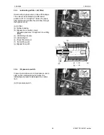
(5)
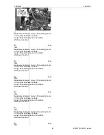
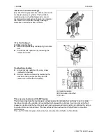
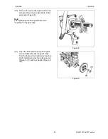
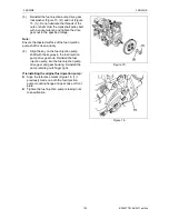
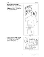
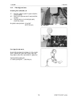
Remove the high-pressure fuel injection
lines as an assembly (Figure 2, (1)).
Note:
To prevent "rounding" the fuel line nuts always
use a "line" or "flare nut" wrench. When
loosening the fuel line nuts, always hold the fuel
injection pump delivery valves with a "back up"
wrench to prevent loosening of the delivery
valves.
(6)
First loosen the fuel line nuts at the fuel
injectors and then at the fuel injection
pump.
CAUTION
Remove or install the high-pressure fuel injection
lines as an assembly whenever possible.
Disassembling the high-pressure fuel injection
lines from the retainers or bending any of the fuel
lines will make it difficult to reinstall the fuel lines.
(7)
Finish loosening all the fuel line nuts and
remove the high-pressure fuel lines as an
assembly being careful not to bend any of
the fuel lines. Be sure to protect the fuel
system from contamination by covering all
open connections.
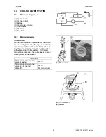
(8)
Disconnect the coolant lines from the cold
start device (Figure 2, (3)) on the fuel
injection pump. Plug the open ends of the
lines to minimize leakage and prevent
contamination.
(9)
Disconnect the fuel return lines from the
fuel return fitting (Figure 2, (2)). Plug the
open ends of the lines to minimize leakage
and prevent contamination.
(10) Remove the fuel supply line (Figure 2, (4)).
Plug the open end of the line to minimize
leakage and prevent contamination.
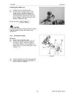
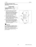
(11) Remove the throttle cable from the fuel
injection pump.
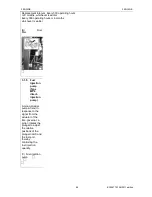
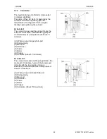
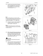
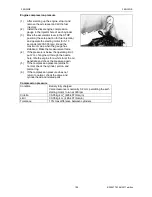
(12) Separate the stop solenoid wiring
connector (Figure 3, (2)).
(13) Remove the rear fuel injection pump
bracket(s) (Figure 3, (1)) from the fuel
injection pump.
Note:
Configuration of the fuel injection pump rear
brackets may vary depending upon engine
model.
Figure 2
Figure 3
Содержание EF-494T
Страница 1: ...EF494T TM 06 2011 edition ...
Страница 30: ...1 PERIODICAL INSPECTION 1 PERIODICAL INSPECTION EF494T TM 06 2011 edition 22 1 PERIODICAL INSPECTION ...
Страница 85: ...3 ENGINE 3 ENGINE EF494T TM 06 2011 edition 77 3 ENGINE ...
Страница 86: ...3 ENGINE 3 ENGINE EF494T TM 06 2011 edition 78 3 1 FUEL SYSTEM 3 1 1 Flow of fuel and layout of components ...
Страница 88: ...3 ENGINE 3 ENGINE EF494T TM 06 2011 edition 80 B Return ...
Страница 126: ...4 CLUTCH 4 CLUTCH EF494T TM 06 2011 edition 118 4 CLUTCH ...
Страница 130: ...4 CLUTCH 4 CLUTCH EF494T TM 06 2011 edition 122 ...
Страница 133: ...5 TRANSMISSION 5 TRANSMISSION EF494T TM 06 2011 edition 125 5 TRANMISSION ...
Страница 136: ...5 TRANSMISSION 5 TRANSMISSION EF494T TM 06 2011 edition 128 5 2 TRANSMISSION SYSTEM CROSS SECTION ...
Страница 158: ...6 REAR AXLE AND BRAKE 6 REAR AXLE AND BRAKE EF494T TM 06 2011 edition 150 6 REAR AXLE AND BRAKE ...
Страница 167: ...7 FRONT AXLE 7 FRONT AXLE EF494T TM 06 2011 edition 159 7 FRONT AXLE ...
Страница 169: ...7 FRONT AXLE 7 FRONT AXLE EF494T TM 06 2011 edition 161 7 2 CROSS SECTION VIEW ...
Страница 176: ...8 POWER STEERING 8 POWER STEERING EF494T TM 06 2011 edition 168 8 POWER STEERING ...
Страница 187: ...9 HYDRAULIC LIFT UNIT 9 HYDRAULIC LIFT UNIT EF494T TM 06 2011 edition 179 9 HYDRAULIC LIFT UNIT ...
Страница 210: ...10 ELECTRIC EQUIPMENT 10 ELECTRIC EQUIPMENT EF494T TM 06 2011 edition 202 10 ELECTRIC EQUIPMENT ...
Страница 214: ...10 ELECTRIC EQUIPMENT 10 ELECTRIC EQUIPMENT EF494T TM 06 2011 edition 206 10 1 2 Circuit diagram Engine start ...
Страница 225: ...10 ELECTRIC EQUIPMENT 10 ELECTRIC EQUIPMENT EF494T TM 06 2011 edition 217 10 3 2 Circuit diagram Alarm ...
Страница 231: ...10 ELECTRIC EQUIPMENT 10 ELECTRIC EQUIPMENT EF494T TM 06 2011 edition 223 10 4 2 Circuit diagram Safety ...
Страница 234: ...11 APPENDIXES 11 APPENDIXES EF494T TM 06 2011 edition 226 11 APPENDIXES ...
Страница 235: ...11 APPENDIXES 11 APPENDIXES EF494T TM 06 2011 edition 227 11 1 HYDRAULIC CIRCUIT DIAGRAM ...
Страница 236: ...228 11 2 ELECTRICAL CIRCUIT DIAGRAM 11 2 1 WIRING HARNESS ...
Страница 238: ...230 11 2 3 ELECTRICAL WIRING DIAGRAM ...
Страница 239: ......