


3 ENGINE
3 ENGINE
EF494T TM 06/2011 edition
101
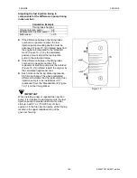
CAUTION
NEVER remove or attempt to remove the
tamper-proof devices from the full-load fuel
adjusting screw or the high-speed throttle limit
screw on the fuel injection pump and governor
assembly. These adjustments have been
made at the factory to meet all applicable
emissions regulations and then sealed.
NEVER attempt to make any adjustments to
these sealed adjustment screws. If
adjustments are required, they can be made
only by a qualified fuel injection shop that will
ensure the injection pump continues to meet
all applicable emissions regulations and then
replace the tamper-proof seals.
Tampering with or removing these devices
may void the "Yanmar Limited Warranty”.
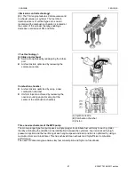
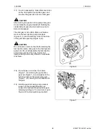
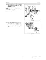
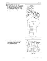
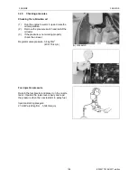
Installation of fuel injection pump
IMPORTANT
If installing a new or recalibrated fuel injection
pump, locate and record the timing index number
located on the pump housing boss on the engine
side of the new or recalibrated fuel injection pump
(Figure 12, (1)) This number will be used to
calculate and adjust the final fuel injection timing.
Note:
If either or both of the fuel injection pumps do not
have a timing index number, note the injection
pump ID (example: XK42) on the injection pump
ID label.
To locate the timing index number for the engine
being serviced use the Timing Index Chart under
"FIE Specs" on the Yanmar Distributor Website
(http://distributor.yanmar. co.jp).
If additional assistance is needed in locating the
engine timing index number See To Locate an
Authorized Yanmar Industrial Engine Dealer or
Distributor- on page 2-4 and follow the instructions
to locate an authorized Yanmar industrial engine
dealer or distributor for assistance.
Note:
Treat the timing index number as if it has a
decimal point (68 = 6.8).
Содержание EF-494T
Страница 1: ...EF494T TM 06 2011 edition ...
Страница 30: ...1 PERIODICAL INSPECTION 1 PERIODICAL INSPECTION EF494T TM 06 2011 edition 22 1 PERIODICAL INSPECTION ...
Страница 85: ...3 ENGINE 3 ENGINE EF494T TM 06 2011 edition 77 3 ENGINE ...
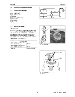
Страница 86: ...3 ENGINE 3 ENGINE EF494T TM 06 2011 edition 78 3 1 FUEL SYSTEM 3 1 1 Flow of fuel and layout of components ...
Страница 88: ...3 ENGINE 3 ENGINE EF494T TM 06 2011 edition 80 B Return ...
Страница 126: ...4 CLUTCH 4 CLUTCH EF494T TM 06 2011 edition 118 4 CLUTCH ...
Страница 130: ...4 CLUTCH 4 CLUTCH EF494T TM 06 2011 edition 122 ...
Страница 133: ...5 TRANSMISSION 5 TRANSMISSION EF494T TM 06 2011 edition 125 5 TRANMISSION ...
Страница 136: ...5 TRANSMISSION 5 TRANSMISSION EF494T TM 06 2011 edition 128 5 2 TRANSMISSION SYSTEM CROSS SECTION ...
Страница 158: ...6 REAR AXLE AND BRAKE 6 REAR AXLE AND BRAKE EF494T TM 06 2011 edition 150 6 REAR AXLE AND BRAKE ...
Страница 167: ...7 FRONT AXLE 7 FRONT AXLE EF494T TM 06 2011 edition 159 7 FRONT AXLE ...
Страница 169: ...7 FRONT AXLE 7 FRONT AXLE EF494T TM 06 2011 edition 161 7 2 CROSS SECTION VIEW ...
Страница 176: ...8 POWER STEERING 8 POWER STEERING EF494T TM 06 2011 edition 168 8 POWER STEERING ...
Страница 187: ...9 HYDRAULIC LIFT UNIT 9 HYDRAULIC LIFT UNIT EF494T TM 06 2011 edition 179 9 HYDRAULIC LIFT UNIT ...
Страница 210: ...10 ELECTRIC EQUIPMENT 10 ELECTRIC EQUIPMENT EF494T TM 06 2011 edition 202 10 ELECTRIC EQUIPMENT ...
Страница 214: ...10 ELECTRIC EQUIPMENT 10 ELECTRIC EQUIPMENT EF494T TM 06 2011 edition 206 10 1 2 Circuit diagram Engine start ...
Страница 225: ...10 ELECTRIC EQUIPMENT 10 ELECTRIC EQUIPMENT EF494T TM 06 2011 edition 217 10 3 2 Circuit diagram Alarm ...
Страница 231: ...10 ELECTRIC EQUIPMENT 10 ELECTRIC EQUIPMENT EF494T TM 06 2011 edition 223 10 4 2 Circuit diagram Safety ...
Страница 234: ...11 APPENDIXES 11 APPENDIXES EF494T TM 06 2011 edition 226 11 APPENDIXES ...
Страница 235: ...11 APPENDIXES 11 APPENDIXES EF494T TM 06 2011 edition 227 11 1 HYDRAULIC CIRCUIT DIAGRAM ...
Страница 236: ...228 11 2 ELECTRICAL CIRCUIT DIAGRAM 11 2 1 WIRING HARNESS ...
Страница 238: ...230 11 2 3 ELECTRICAL WIRING DIAGRAM ...
Страница 239: ......