4-4
4
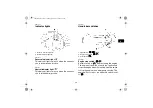
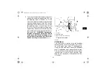
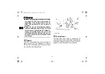
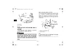
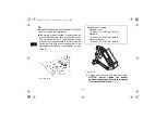
2. To increase the maximum engine power avail-
able and the maximum speed of the ATV, turn
the adjusting screw in direction (a). To de-
crease the maximum engine power available
and the maximum speed of the ATV, turn the
adjusting screw in direction (b). Do not turn
the adjusting screw out more than 12 mm
(0.47 in) or the throttle cable could be dam-
aged. Always make sure the throttle lever free
play is adjusted to 2.0–4.0 mm (0.08–0.16 in).
(See page 8-21.)
WARNING! Improper ad-
justment of the speed limiter and throttle
could cause throttle cable damage or im-
proper throttle operation. You could lose
control, resulting in an accident.
[EWB00241]
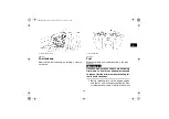
3. Tighten the locknut.
EBU18382
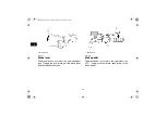
Clutch lever
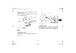
The clutch lever is located on the left handlebar
and the ignition circuit cut-off system is incorporat-
ed in the clutch lever holder. To disengage the
clutch, pull the clutch lever toward the handlebar
grip. To engage the clutch, release the clutch lever.
The clutch lever should be pulled rapidly and re-
leased slowly for smooth clutch operation. (See
page 6-1 for a description of the ignition circuit cut-
off system.)
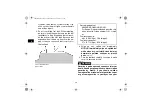
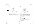
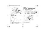
1. Locknut
2. Adjusting screw
3. No more than 12 mm (0.47 in)
U1BS60E0.book Page 4 Thursday, April 16, 2009 4:11 PM
Содержание YFM350RZ
Страница 12: ...1 2 1 4D3 2816L 20 43P 2816R 00 1 2 3 U1BS60E0 book Page 2 Thursday April 16 2009 4 11 PM ...
Страница 17: ...1 7 1 For Oceania 1 2 3 4 5 U1BS60E0 book Page 7 Thursday April 16 2009 4 11 PM ...
Страница 57: ...7 1 7 EBU21141 RIDING YOUR ATV U1BS60E0 book Page 1 Thursday April 16 2009 4 11 PM ...
Страница 135: ...11 3 11 1 Model label U1BS60E0 book Page 3 Thursday April 16 2009 4 11 PM ...

