background image

4 - 80

CHAS

FRONT FORK

EAS00659

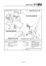
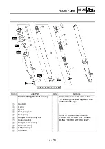
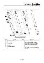
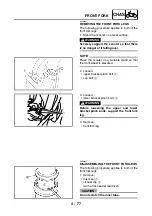
ASSEMBLING THE FRONT FORK LEGS

The following procedure applies to both of the
front fork legs.

WARNING

• Make sure that the oil levels in both front

fork legs are equal.

• Uneven oil levels can result in poor han-

dling and a loss of stability.

NOTE:

• When assembling the front fork leg, be sure

to replace the following parts:

- inner tube bushing
- outer tube bushing
- oil seal
- dust seal

• Before assembling the front fork leg, make

sure that all of the components are clean.

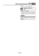
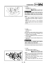
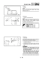
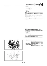
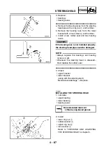
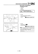
1. Install:

• damper rod 

1

• rebound spring 

2

CAUTION:

Allow the damper rod to slide slowly down
the inner tube 

3

 until it protrudes from the

bottom of the inner tube. Be careful not to
damage the inner tube.

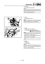
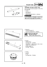
2. Install:

• oil flow stopper 

1

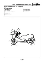
3. Lubricate:

• inner tube’s outer surface 

2

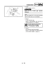
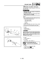
4. Install:

• outer tube (onto the inner tube)
• copper washer
• damper rod assembly bolt

Recommended lubricant

Fork oil 7.5 W or equivalent

1

2

New

Содержание XP500

Страница 1: ...2005 XP500 XP500A5VU5 AE1 SERVICE MANUAL...

Страница 2: ......

Страница 3: ...500A 2005 SERVICE MANUAL 2004 by Yamaha Motor Co Ltd First edition September 2004 All rights reserved Any reproduction or unauthorized use without the written permission of Yamaha Motor Co Ltd is expr...

Страница 4: ...models Modifications and significant changes in specifications or procedures will be forwarded to all authorized Yamaha deal ers and will appear in future editions of this manual where applicable NOTE...

Страница 5: ...age except in Chapter 3 PERIODIC CHECKS AND ADJUSTMENTS where the sub section title s appears 3 Sub section titles appear in smaller print than the section title 4 To help identify parts and clarify p...

Страница 6: ...fluid B Lubricant C Special tool D Tightening torque E Wear limit clearance F Engine speed G Electrical data Symbols H to M in the exploded diagrams indicate the types of lubricants and lubrication p...

Страница 7: ...GENERAL INFORMATION GEN INFO 1 SPECIFICATIONS SPEC 2 PERIODIC CHECKS AND ADJUSTMENTS CHK ADJ 3 CHASSIS CHAS 4 ENGINE ENG 5 COOLING SYSTEM COOL 6 FUEL INJECTION SYSTEM FI 7 ELECTRICAL SYSTEM ELEC 8 TR...

Страница 8: ......

Страница 9: ...GEN INFO 1...

Страница 10: ...1 2 FI SYSTEM 1 3 OUTLINE OF ANTI LOCK BRAKE SYSTEM XP500A 1 4 INSTRUMENT FUNCTION 1 15 IMPORTANT INFORMATION 1 19 PREPARATION FOR REMOVAL AND DISASSEMBLY 1 19 REPLACEMENT PARTS 1 19 GASKETS OIL SEALS...

Страница 11: ...GEN INFO...

Страница 12: ...EAS00017 VEHICLE IDENTIFICATION NUMBER The vehicle identification number 1 is stamped into the right side of the frame EAS00018 MODEL LABEL The model label 2 is affixed to the storage box This inform...

Страница 13: ...es to deliver more performance and cleaner exhaust gases increase it becomes necessary to control the air fuel ratio in a more precise and finely tuned manner To accommodate this need this model has a...

Страница 14: ...e lesser the volume of fuel that is supplied The injection duration and the injection timing are controlled by the ECU engine Signals that are input from the throttle position sensor crankshaft positi...

Страница 15: ...brake and a left hand brake lever for operating the rear wheel brake When wheel lockup is detected during emergency braking hydraulic control is performed by the hydraulic system independently EAS0087...

Страница 16: ...e master cylinder 2 Hydraulic unit 3 Hydraulic pump 4 ABS motor 5 Buffer chamber 6 Hydraulic control valve 7 Front brake master cylinder 8 Rear brake caliper 9 Front brake caliper 0 ECU ABS A Rear whe...

Страница 17: ...th of the wheels has stopped but the vehicle continues to travel Side force The force on the tires which supports the vehicle when cornering Slip ratio When the brakes are applied slipping occurs betw...

Страница 18: ...e Less slippery road surface Controlling zone Slippery road surface Slip ratio EAS00875 Wheel slip and hydraulic control The ECU ABS calculates the wheel speed of each wheel according to the rotation...

Страница 19: ...se the tire to slip sideways WARNING _ The braking of the vehicle even in the worst case is principally executed when the vehicle is advancing straight ahead During a turn sudden braking is liable to...

Страница 20: ...sing As the distance changes between the top and bottom of the serrations with the rotation of the wheels inductive electromotive force is generated in the wheel sensors Wheel rotation speed is detect...

Страница 21: ...1 000 of a second When a failure is detected in the ABS a malfunction code is stored in the memory of the ECU ABS for easy problem identification and troubleshoot ing NOTE _ Some types of failures ar...

Страница 22: ...draulic pressure of the brake fluid and normal braking is resumed The ABS motor relay is also activated by signals transmitted from the ECU ABS and operates simultaneously when the ABS starts to reduc...

Страница 23: ...inder increases and the brake fluid is sent to the brake caliper via port A and port B At this time the inlet and outlet check valves of the pump close the lines and brake fluid is not sent As a resul...

Страница 24: ...orifice 0 and the brake fluid is sent to the brake caliper via port C C and port D A and the buffer chamber As a result the hydraulic pressure in the brake caliper is reduced The brake fluid stored i...

Страница 25: ...t A 7 and port C C At this time the brake is pressurized at a constant speed regardless of the brake fluid pressure level since restriction of port A 7 changes so that a constant pressure difference i...

Страница 26: ...d ABS 3 a clock 4 an oil change indicator 5 a V belt replacement indicator 6 a fuel level warning symbol 7 a coolant temperature symbol 8 NOTE Be sure to turn the key to ON before using the SELECT 9 a...

Страница 27: ...fueling and traveling 5 km 3 mi Fuel meter With the key in the ON position the fuel meter indicates the amount of fuel in the fuel tank The display segments of the fuel meter disappear towards E Empty...

Страница 28: ...goes off 3 If the indicator does not come on check the electrical circuit Refer to SIGNALING SYSTEM in chapter 8 NOTE The oil change indicator may flash when the engine is revved with the scooter on t...

Страница 29: ...replacement indica tor will come on for 1 4 seconds And the V belt replacement indicator will go off NOTE If the V belt is replaced before the V belt replacement indicator comes on i e before the V be...

Страница 30: ...an all of the parts and place them in trays in the order of dis assembly This will speed up assembly and allow for the correct installation of all parts 5 Keep all parts away from any source of fire E...

Страница 31: ...sible When installing oil seals lubricate the oil seal lips with a light coat of lithium soap based grease Oil bearings liberally when installing if appro priate 1 Oil seal CAUTION _ Do not spin the b...

Страница 32: ...nect sev eral times 3 Check all connections Loose connection Connect properly NOTE _ If the pin 1 on the terminal is flattened bend it up 4 Connect lead coupler connector NOTE _ Make sure all connecti...

Страница 33: ...Illustration 90890 01235 YU 01235 Rotor holding tool This tool is used to hold the clutch assembly 90890 01268 YU 01268 Ring nut wrench This tool is used to loosen or tighten the steering ring nuts 90...

Страница 34: ...nut wrench This tool is used to loosen or tighten the steering ring nuts 90890 01469 Oil filter wrench This tool is needed to loosen or tighten the oil filter cartridge 90890 01481 Sheave holder This...

Страница 35: ...03112 YU 03112 C Pocket tester This tool is used to check the electrical system 90890 03141 YM 33277 B Timing light This tool is used to check the ignition tim ing 90890 03149 Test coupler adaptor Th...

Страница 36: ...ver 90890 04058 YM 04058 Mechanical seal installer 90890 04078 YM 33221 A Middle driven shaft bearing driver Mechanical seal installer These tools are used to install the water pump seal 90890 04085 D...

Страница 37: ...ressor Sheave fixed block This tool is used to hold the compression spring when removing or installing the secondary sheave nut 90890 04139 Plane bearing installer This tool is used to install the cra...

Страница 38: ...SPEC 2...

Страница 39: ...RAL TIGHTENING TORQUE SPECIFICATIONS 2 18 TIGHTENING TORQUES 2 19 ENGINE TIGHTENING TORQUES 2 19 CHASSIS TIGHTENING TORQUES 2 22 LUBRICATION POINTS AND LUBRICANT TYPES 2 24 ENGINE LUBRICATION POINTS A...

Страница 40: ...SPEC...

Страница 41: ...Overall height 1 410 mm 55 5 in Seat height 795 mm 31 3 in Wheelbase 1 575 mm 62 0 in Minimum ground clearance 130 mm 5 12 in Minimum turning radius 2 800 mm 110 2 in Weight Wet with oil and a full fu...

Страница 42: ...70 C 158 F Fuel Recommended fuel Regular unleaded gasoline only Fuel tank capacity Total including reserve 14 L 3 08 Imp gal 3 70 US gal Engine oil Lubrication system Dry sump Recommended oil SAE10W3...

Страница 43: ...32 Imp qt 1 59 US qt Coolant reservoir capacity up to the maximum level mark 0 35 L 0 31 Imp qt 0 37 US qt Radiator cap opening pressure 107 9 137 3 kPa 1 08 1 37 kg cm2 15 6 19 9 psi Radiator core Wi...

Страница 44: ...n Intake camshaft lobe dimensions Measurement A 33 252 33 352 mm 1 3091 1 3131 in 33 152 mm 1 3052 in Measurement B 24 956 25 056 mm 0 9825 0 9865 in 24 856 mm 0 9786 in Exhaust camshaft lobe dimensio...

Страница 45: ...33 in 1 6 mm 0 06 in Valve margin thickness D Intake 0 6 0 8 mm 0 0236 0 0315 in 0 5 mm 0 0197 in Exhaust 0 6 0 8 mm 0 0236 0 0315 in 0 5 mm 0 0197 in Valve stem diameter Intake 3 975 3 990 mm 0 1565...

Страница 46: ...30 39 mm 1 20 in Exhaust 30 39 mm 1 20 in Spring rate K1 Intake 18 84 N mm 1 92 kg mm 107 60 lb in Exhaust 18 84 N mm 1 92 kg mm 107 60 lb in Spring rate K2 Intake 24 52 N mm 2 50 kg mm 140 01 lb in E...

Страница 47: ...0020 in Maximum out of round 0 05 mm 0 0020 in Pistons Piston to cylinder clearance 0 020 0 045 mm 0 0008 0 0018 in 0 15 mm 0 0059 in Diameter D 65 965 65 980 mm 2 5970 2 5976 in Height H 9 0 mm 0 35...

Страница 48: ...in End gap installed 0 40 0 50 mm 0 0157 0 0197 in 0 75 mm 0 0295 in Ring side clearance 0 020 0 055 mm 0 0008 0 0022 in 0 10 mm 0 0039 in Oil ring Dimensions B T 1 50 2 00 mm 0 06 0 08 in End gap ins...

Страница 49: ...in Bearing color code 1 Blue 2 Black 3 Brown 4 Green Balancer Balancer drive method Piston Clutch Clutch type Wet multiple disc automatic Clutch release method Automatic Friction plates Thickness 2 75...

Страница 50: ...tem Chain drive Secondary reduction ratio 41 25 40 29 2 262 Operation Centrifugal automatic type Maximum main axle runout 0 08 mm 0 0031 in Maximum drive axle runout 0 08 mm 0 0031 in Air filter type...

Страница 51: ...25 mm 0 01 in Rear wheel Wheel type Cast wheel Rim Size 15M C MT5 00 Material Aluminum Wheel travel 117 mm 4 61 in Wheel runout Maximum radial wheel runout 1 mm 0 04 in Maximum lateral wheel runout 0...

Страница 52: ...7 0 4 0 mm 10 51 0 16 in Minimum thickness 3 5 mm 0 14 in Maximum deflection 0 12 mm 0 0047 in Brake pad lining thickness 6 2 mm 0 24 in 0 8 mm 0 03 in Master cylinder inside diameter 14 00 mm 0 55 in...

Страница 53: ...1 US qt Level 109 0 mm 4 29 in Inner tube outer diameter 41 0 mm 1 61 in Inner tube bending limit 0 2 mm 0 01 in Steering Steering bearing type Angular ball bearing Lock to lock angle left 38 5 Lock t...

Страница 54: ...he end of the swing arm Radial 1 0 mm 0 04 in Axial 1 0 mm 0 04 in Secondary drive chain Model manufacturer 23RH303 5 82ASM Borg warner Link quantity 82 Primary drive chain Model manufacturer 89HV302...

Страница 55: ...24 in Primary coil resistance 1 87 2 53 at 20 C 68 F Secondary coil resistance 12 18 k at 20 C 68 F Spark plug cap Material Resin Resistance 10 0 k at 20 C 68 F Charging system System type A C magneto...

Страница 56: ...r motor Model manufacturer SM 13 MITSUBA Power output 0 7 kW Brushes Overall length 12 0 mm 0 47 in 4 0 mm 0 16 in Spring force 7 65 10 01 N 780 1 021 gf 27 53 36 04 oz Commutator resistance 0 0015 0...

Страница 57: ...10 0 326 k Resistance at 110 C 230 F 0 140 0 144 k Fuses Main fuse 30 A Headlight fuse 15 A Signaling system fuse 20 A XP500 15 A XP500A Ignition fuse 10 A Radiator fan motor fuse 15 A Lighting system...

Страница 58: ...ied tightening torque specifications require clean dry threads Com ponents should be at room temperature A Distance between flats B Outside thread diameter Ex METRIC MULTIPLIER IMPERIAL mm 0 03937 in...

Страница 59: ...housing cover Bolt M6 2 10 1 0 7 2 Water pump assembly Bolt M6 2 10 1 0 7 2 Coolant pipe Bolt M6 2 10 1 0 7 2 Radiator filler neck Bolt M6 1 7 0 7 5 1 Radiator drain bolt Screw M12 1 1 6 0 16 1 2 Wat...

Страница 60: ...1 90 9 0 65 Clutch assembly Nut M16 1 65 6 5 47 Chain drive holder assembly Bolt M8 3 30 3 0 22 Chain drive drain bolt Bolt M12 1 20 2 0 14 Chain drive case outer Bolt M6 18 10 1 0 7 2 Chain drive cas...

Страница 61: ...2 21 SPEC TIGHTENING TORQUES Crankcase tightening sequence Cylinder head tightening sequence 1 8 M8 Bolt 9 21 M6 Bolt...

Страница 62: ...43 Front wheel axle pinch bolt M8 23 2 3 17 Rear wheel axle nut M14 100 10 0 72 Rear wheel axle pinch bolt M8 17 1 7 12 Front brake caliper bracket M10 40 4 0 29 Front brake caliper retaining bolt M10...

Страница 63: ...r moulding and passenger foot rest M6 7 0 7 5 1 Rear side cover and frame M6 7 0 7 5 1 Leg shield footrest board and frame M6 7 0 7 5 1 Footrest board and frame M6 7 0 7 5 1 Seat damper M8 16 1 6 11 F...

Страница 64: ...nals E Camshaft lobs M Camshaft journals M Camshaft cap M Valve stems intake and exhaust M Valve stem ends intake and exhaust E Cylinder head nut E Water pump impeller shaft M Oil pump shaft E Oil pum...

Страница 65: ...sembly lube Swingarm pivot shaft bearing LS Crankcase mating surface Yamaha bond No 1215 A C magneto lead Yamaha bond No 1215 Cylinder head cover gasket mating surface Yamaha bond No 1215 Cylinder hea...

Страница 66: ...ts left and right LS Parking brake lock lever cable and parking brake lock lever cable connec tion area LS Sidestand pivoting point metal to metal moving parts LS Centerstand shaft pivoting point and...

Страница 67: ...27 SPEC OIL FLOW DIAGRAMS OIL FLOW DIAGRAMS 1 Oil pump 2 Oil tank 3 Oil strainer 4 Relief valve 5 Oil cooler 6 Oil filter cartridge 7 Exhaust camshaft 8 Intake camshaft 9 Oil pipe 0 Oil delivery pipe...

Страница 68: ...2 28 SPEC OIL FLOW DIAGRAMS 1 Oil strainer 2 Crankshaft...

Страница 69: ...2 29 SPEC OIL FLOW DIAGRAMS 1 Clutch 2 Right main journal bearing 3 Main gallery plug...

Страница 70: ...SPEC OIL FLOW DIAGRAMS Exhaust camshaft Intake camshaft Piston cooler Crankshaft Oil tank Oil filter cartridge Oil cooler Relief valve Check valve Flush oil pump Suction oil pump Strainer Strainer Oil...

Страница 71: ...2 31 SPEC COOLANT FLOW DIAGRAMS EAS00035 COOLANT FLOW DIAGRAMS 1 Coolant reservoir 2 Thermostat 3 Radiator 4 Water pump 5 Radiator fan 6 Radiator cap 7 Fast idle plunger 1 2 3 5 6 2 3 6 4 7...

Страница 72: ...om being pulled out by the headlight assembly left and right Connect the headlight sub wire harness to the wire harness on top of the stay left and right After making the connection push the coupler b...

Страница 73: ...arness guide to hold down the wire harness Route the throttle cables between handle under cover and upper bracket Route the throttle cables through the hole of the lower handlebar cover Connect the br...

Страница 74: ...2 34 SPEC CABLE ROUTING Fasten the right handlebar switch leads to the handlebar with a plastic band Route the rear brake hose and left handlebar switch leads over the wire harness...

Страница 75: ...dlebar and the upper bracket Fasten the wire harness by sliding the plastic holder on the wire harness onto the stud on the handlebar Fasten the grommets on the brake hoses with the holder Install the...

Страница 76: ...ank breather hose B Rear footrest assembly C Fuel tank breather hose D Hose holder E Hose holder F Fuel hose G Fuel pump lead H Hose guide I Roll over valve assembly J Holder K Fuel pump L Fuel pump b...

Страница 77: ...f frame 50 70 mm 1 97 2 76 in 2 5 mm 0 08 0 20 in Install the grommet to the footrest board securely Install the grommet to the fuel tank securely Make sure that the clip end faces to the front side I...

Страница 78: ...e guide Pass the fuel hose to the inside of the frame guide After connecting the fuel hose connector to the fuel tank install the fuel hose connector cover completely onto the connector Install and re...

Страница 79: ...ensor coupler B Starter motor lead C Rectifier regulator D Starting circuit cut off relay 1 E Turn signal hazard relay F O2 sensor G V belt replacement indicator reset coupler H O2 sensor coupler I Fu...

Страница 80: ...tightly Pass the seat lock cable between wire harness and frame Use the plastic holder on the back of the frame to hold the radiator fan motor lead Connect the wire harness wire taped area to the T st...

Страница 81: ...e stay 1 with a plastic holder Fasten the ECU engine lead to the stay 1 with a plastic holder When fastening them using a plastic holder make sure not to cross the branch leads Fasten the coolant rese...

Страница 82: ...ve battery lead and seat lock cable right to the frame with a plastic holder Fasten the starter motor lead and negative bat tery lead to the frame with a plastic holder Fasten the wire harness to the...

Страница 83: ...cover Fasten the O2 sensor lead and V belt replace ment indicator reset coupler lead to the frame with a plastic holder Pass the wire harness and seat lock cable in the frame holder Pass the rear brak...

Страница 84: ...astened part between frame and storage box Route the seat lock cable through the frame bracket side and under the wire harness T stud for position setting A F A G A H A I A J J A A B B C C D D E E F F...

Страница 85: ...eather hose 7 Coolant hose 8 Sidestand switch 9 Fast idle outlet hose 0 Radiator outlet hose A Crankcase breather hose B Throttle cable accelerator cable single locknut Pass the rear brake lock lever...

Страница 86: ...alling the rear footrest do not catch or pinch the A C magneto lead in the bracket Fasten the wire harness to the frame with a plas tic holder Pass the storage box light switch lead by the front of th...

Страница 87: ...circuit cut off relay 1 0 Rectifier regulator A Seat lock B Battery C Positive battery lead D Fuel pump lead E Fuel overflow hose F Intake air pressure sensor G Meter assembly coupler H Intake air te...

Страница 88: ...d hose to the frame with a plastic holder Fasten the rear brake lock lever cable to the frame with a plastic holder Be sure not to pinch the storage box light switch lead when installing the fuel tank...

Страница 89: ...he seat lock cable black to the right seat lock Route the negative battery lead and the fuse box lead from the storage box opening to the bottom of the cross pipe Route the fuse box lead above the sta...

Страница 90: ...ble to the mad guard with a plastic holder Route the positive battery lead through the under the seat lock cable Fasten the wire harness to the frame with a plas tic holder Connect the seat lock cable...

Страница 91: ...and to the inside of the frame 10 15 mm 0 39 0 59 in Route the wire harness through the wire guide Pass the speed sensor lead under the stay 1 and cross pipe and then over the brake hose guide Place t...

Страница 92: ...rake lock lever cable 9 Rear brake hose 0 Speed sensor lead Pass the rear brake lock lever cable on the front side of throttle cable Position of clamp Position the relay straighten Fasten the cooling...

Страница 93: ...BLE ROUTING Fasten the sidestand switch lead to the frame with a plastic holder Fasten the rear brake hose to the stay 1 with a plastic holder Route the throttle cable through the cable holder 2 4 5 6...

Страница 94: ...g the inside of the brake hose 50 60 mm 1 97 2 36 in Turn the handlebar completely to the right and then fasten the brake hose and speed sensor lead together with the plastic holder Install the stoppe...

Страница 95: ...he hose holder to the innermost securely Engage the hose holder rib more than 3 notch Face the hose holder projection to the back Make sure that the white paint on the brake hose faces to back right s...

Страница 96: ...tor fan motor lead D Starter motor lead E Rectifier regulator F Starting circuit cut off relay 2 G Starting circuit cut off relay 1 H Turn signal hazard relay I O2 sensor J V belt replacement indicato...

Страница 97: ...tery lead T Rear wheel sensor lead U Frame V Storage box W V belt replacement indicator reset coupler lead X O2 sensor lead Y Fuel hose A A B B D D F F J J K K H H C C E E G G I I P P C B O Q D R T D...

Страница 98: ...on coil bracket then to the outside of the frame Fasten the wire harness main switch lead and seat lock cable with the plastic band under the stay 1 Be sure to fasten the seat lock cable on the metal...

Страница 99: ...b wire harness to the stay 1 with a plastic holder When fastening them using a plastic holder make sure not to cross the branch leads Fasten the coolant reservoir hose to the stay 1 with a plastic hol...

Страница 100: ...re that the seat lock cable do not lean over the storage box Fasten the starter motor lead negative battery lead and seat lock cable left to the frame with a plastic holder Fasten the starter motor le...

Страница 101: ...or reset coupler lead to the frame with a plastic holder Pass the wire harness and seat lock cable in the frame holder Pass the rear brake lock lever cable under the coolant pipe 40 50 mm 1 57 1 97 in...

Страница 102: ...into the space inside the frame above the mudguard Insert the tail brake light coupler between the wire harness and the seat lock cable left 20 30 mm 0 79 1 18 in To the tail brake light Route the ta...

Страница 103: ...ll the band s fastened part between frame and storage box A Q A R A S A A B B D D F F J J K K H H C C E E G G I I P P C B O Q D R T D D T P U U U P U V S W N X P Q Q N A A B B B 9 8 7 6 5 2 1 AR AD AC...

Страница 104: ...tank breather hose 7 Coolant hose 8 Sidestand switch 9 Fast idle outlet hose 0 Radiator outlet hose A Crankcase breather hose B Throttle cable accelerator cable single locknut Pass the rear brake loc...

Страница 105: ...or pinch the A C magneto lead in the bracket Fasten the wire harness to the frame with a plas tic holder Pass the storage box light switch lead by the front of the frame back stay pipe Fasten the sid...

Страница 106: ...egulator A Starter motor lead B Battery C Seat lock D Positive battery lead E Fuel pump lead F Fuel overflow hose G Intake air pressure sensor H Hydraulic unit solenoid coupler I ABS motor coupler J M...

Страница 107: ...lastic holder Fasten the rear brake lock lever cable to the frame with a plastic holder Be sure not to pinch the storage box light switch lead when installing the fuel tank Connect the fuel injector l...

Страница 108: ...Place the rubber cover over the starter relay starter relay coupler positive battery lead termi nal and starter motor lead terminal Align the plastic clamp with the white tape on the wire harness and...

Страница 109: ...se box assembly to the storage box Connect the ABS motor fuse box to the fuse box 2 Install the storage box light switch to the storage box Fasten the negative battery lead and the starter motor lead...

Страница 110: ...uide Pass the front wheel sensor lead under the stay 1 and cross pipe Place the front wheel sensor lead between the ribs of the air filter case Fasten the protective tube around the lean angle cut off...

Страница 111: ...Spark plug lead 2 9 Radiator fan motor lead 0 Sidestand switch lead A Spark plug lead 1 B Rear brake lock lever cable C Stay 1 D Rear brake hose E Hydraulic unit F Hydraulic unit solenoid coupler G Fr...

Страница 112: ...tside of the frame Fasten the fuel injection leads with a plastic holder Fasten the sidestand switch lead to the frame with a plastic holder Fasten the storage box light switch lead to the frame with...

Страница 113: ...se hydraulic unit to rear brake caliper A Brake hose hydraulic unit to front brake caliper Route the front wheel sensor lead in front of the brake hose hydraulic unit to front brake cali pers as shown...

Страница 114: ...f the hose extends 70 100 mm 2 76 3 94 in past the holder 40 60 mm 1 57 2 36 in 70 100 mm 2 76 3 94 in Install the brake hose hydraulic unit to front brake caliper onto the hydraulic unit The brake ho...

Страница 115: ...d between the ends of the upper and lower ECU ABS brackets Fasten the grommets on the brake hose front brake master cylinder to hydraulic unit and the brake hose rear brake master cylinder to hydrauli...

Страница 116: ...hose holder projection to the back Make sure that the white paint on the brake hose faces to back right side only Install the hose holder to the innermost securely Turn the handlebar completely to the...

Страница 117: ...etween the brake hose and front fork Make sure that the stopper touches the outer tube stay 30 40 mm 1 18 1 57 in Make sure that brake pipe touches the projec tion Make sure that the slot in the senso...

Страница 118: ......

Страница 119: ...CHK ADJ 3...

Страница 120: ...0 ADJUSTING THE ENGINE IDLING SPEED 3 22 ADJUSTING THE THROTTLE CABLE FREE PLAY 3 23 CHECKING THE SPARK PLUGS 3 25 CHECKING THE IGNITION TIMING 3 26 MEASURING THE COMPRESSION PRESSURE 3 27 CHECKING TH...

Страница 121: ...YSTEM XP500A 3 50 CHECKING AND ADJUSTING THE STEERING HEAD 3 53 CHECKING THE FRONT FORK 3 56 CHECKING THE TIRES 3 57 CHECKING THE WHEELS 3 59 CHECKING AND LUBRICATING THE CABLES 3 60 LUBRICATING THE L...

Страница 122: ...AINTENANCE JOB ODOMETER READING 1000 km ANNUAL CHECK 1 10 20 30 40 1 Fuel line See page 3 37 Check fuel hoses for cracks or damage 2 Spark plugs See page 3 25 Check condition Clean and regap Replace 3...

Страница 123: ...heck operation and shock absorber for oil leak age 19 Electronic fuel injection See page 3 17 3 22 Adjust engine idling speed and synchronization 20 Engine oil See page 3 30 Change When the oil change...

Страница 124: ...3 3 CHK ADJ SEAT SEAT 1 2 Order Job Part Q ty Remarks Removing the seat Removing the parts in the order listed 1 Fuel lid 1 2 Seat 1 For installation reverse the removal pro cedure...

Страница 125: ...s in the order listed 1 Footrest board mat left and right 2 2 Front side cover moulding left and right 2 3 Rearview mirror left and right 2 4 Front cowling upper cover 1 5 Windshield 1 6 Front cowling...

Страница 126: ...rder listed 1 Upper side cover mole left and right 2 2 Lower side cover mole left and right 2 3 Center cover 1 4 Hinge cover 1 5 Side cover left and right 2 6 Footrest board left and right 2 7 Coolant...

Страница 127: ...light assembly Removing the parts in the order listed Seat Open Upper side cover mole left and right Refer to SIDE COVER MOULDINGS AND LEG SHIELD 1 Grab bar 1 2 Rear cover 1 3 Rear side cover left an...

Страница 128: ...Nm 0 7 m kg 5 1 ft Ib Order Job Part Q ty Remarks Removing the fuel tank Remove the parts in the order listed 1 Battery cover 1 2 Negative battery lead 1 Disconnect 3 Positive battery lead 1 Disconne...

Страница 129: ...ob Part Q ty Remarks 14 Fuel pump coupler 1 Disconnect Refer to REMOVING THE FUEL TANK and INSTALLING THE FUEL TANK 15 Fuel hose connector cover 1 16 Fuel hose 1 17 Fuel tank breather hose 1 18 Fuel p...

Страница 130: ...lthough the fuel has been removed from the fuel tank be careful when removing the fuel hoses since there may be fuel remaining in it Do not disconnect the fuel hose except the fuel hose connector of t...

Страница 131: ...on shown in the illustration 1 2 3 4 5 6 FWD a New T R 4 Nm 0 4 m kg 2 9 ft lb INSTALLING THE FUEL TANK 1 Install fuel tank NOTE Tighten the bolts to the specified torque in the proper tightening sequ...

Страница 132: ...justed the piston must be at top dead center TDC on the compression stroke 1 Remove front cowling Refer to FRONT COWLING footrest boards leg shield inner fender Refer to SIDE COVER MOULDINGS AND LEG S...

Страница 133: ...piston is at TDC the alignment mark c on the intake cam shaft sprocket and the alignment mark d on the exhaust camshaft sprocket must align with the cylinder head mating surface as shown in the illust...

Страница 134: ...prevent the valve pad from falling into the crankcase Make a note of the position of each valve lifter 1 and valve pad 2 so that they can be installed in the correct place b Select the proper valve pa...

Страница 135: ...and row intersect is the new valve pad number NOTE The new valve pad number is only an approxi mation The valve clearance must be mea sured again and the above steps should be repeated if the measurem...

Страница 136: ...ust camshaft Align the camshaft sprocket marks with the edge of the cylinder head Turn the crankshaft counterclockwise sev eral turns to seat the parts g Measure the valve clearance again h If the val...

Страница 137: ...1 27 230 235 240 1 28 1 32 235 240 1 33 1 37 240 MEASURED VALVE CLEARANCE ORIGINAL VALVE PAD NUMBER 120 125 130 135 140 145 150 155 160 165 170 175 180 185 190 195 200 205 210 215 220 225 230 235 240...

Страница 138: ...engine idling speed should be properly adjusted and the ignition timing should be checked 1 Stand the scooter on a level surface NOTE Place the scooter on a suitable stand 2 Remove seat Refer to SEAT...

Страница 139: ...ess than a second and check the synchronization again If the air screw is removed turn the screw 3 4 turn in and be sure to synchronize the throttle body CAUTION Do not use the throttle valve adjustin...

Страница 140: ...AUST GAS VOLUME NOTE Be sure to set the CO density level to stan dard and then adjust the exhaust gas volume 1 Turn the main switch to OFF and set the engine stop switch to 2 Simultaneously press and...

Страница 141: ...ment volume by pressing the SELECT 1 and RESET 2 buttons NOTE The CO adjustment volume appears on the tripmeter LCD To decrease the CO adjustment volume press the RESET button To increase the CO adjus...

Страница 142: ...ust Refer to ADJUSTING THE ENGINE IDLING SPEED Pocket tester 90890 03112 YU 03112 C Oil temperature 70 C 158 F Engine idling speed 1 100 1 300 r min 1 6 Install CO HC tester 1 sampling probe 2 NOTE Si...

Страница 143: ...ion should be adjusted properly and the engine should have adequate compression 1 Remove right side cover Refer to SIDE COVER MOULDINGS AND LEG SHIELD 2 Start the engine and let it warm up for sev era...

Страница 144: ...the flange of the throttle grip 3 5 mm 0 12 0 20 in EAS00055 ADJUSTING THE THROTTLE CABLE FREE PLAY NOTE Prior to adjusting the throttle cable free play the engine idling speed and throttle bodies sy...

Страница 145: ...ined d Tighten the locknuts NOTE If the specified throttle cable free play cannot be obtained on the throttle body side of the cable use the adjusting nut on the handlebar side Direction a Throttle ca...

Страница 146: ...cover Refer to SIDE COVER MOULDINGS AND LEG SHIELD CHECKING THE SPARK PLUGS The following procedure applies to all of the spark plugs 1 Remove center cover side cover left and right inner fender Refe...

Страница 147: ...the spark plug clean the spark plug and gasket surface 9 Connect spark plug caps 10 Install Inner fender side cover left and right center cover Refer to SIDE COVER MOULDINGS AND LEG SHIELD EAS00062 CH...

Страница 148: ...ry pointer a is within the firing rang b on the A C magneto Incorrect firing range Check the ignition system NOTE The ignition timing is not adjustable 5 Install timing plug 6 Install left footrest bo...

Страница 149: ...plug cap 5 Remove spark plug CAUTION Before removing the spark plugs use com pressed air to blow away any dirt accumu lated in the spark plug wells to prevent it from falling into the cylinders 6 Ins...

Страница 150: ...ad valve surfaces and piston crown for carbon deposits Carbon deposits Eliminate d If the compression pressure is below the minimum specification pour a teaspoonful engine of oil into the spark plug b...

Страница 151: ...the minimum level mark Add the recommended engine oil to the proper level CAUTION Engine oil also lubricates the clutch and the wrong oil types or additives could cause clutch slippage Therefore do no...

Страница 152: ...ter wrench 2 b Lubricate the O ring 3 of the new oil filter cartridge with a thin coat of engine oil CAUTION Make sure that the O ring is positioned cor rectly in the groove of the oil filter car trid...

Страница 153: ...go off NOTE If the engine oil is changed before the oil change indicator light comes on i e before the periodic oil change interval has been reached the indicator light must be reset after the oil cha...

Страница 154: ...tart the engine warm it up for several min utes and then turn it off CAUTION When the engine is cold the engine oil will have a higher viscosity causing the engine oil pressure to increase Therefore b...

Страница 155: ...158 F Engine oil pressure Possible causes Below specification Faulty oil pump Clogged oil filter Leaking oil passage Broken or damaged oil seal Above specification Leaking oil passage Faulty oil filt...

Страница 156: ...ll also affect the carburetor tuning leading to poor engine performance and possible overheat ing NOTE When installing the air filter element into the air filter case cover be sure their sealing surfa...

Страница 157: ...k V belt case air filter element Damage Replace CAUTION Since the V belt case air filter element is a dry type do not let grease or water contact it 6 Install V belt case air filter element right V be...

Страница 158: ...Refer to THROTTLE BODY in chapter 7 3 Install leg shield Refer to SIDE COVER MOULDINGS AND LEG SHIELD 1 2 EAS00097 CHECKING THE FUEL HOSES AND FUEL TANK BREATHER HOSE The following procedure applies...

Страница 159: ...e following procedure applies to all of the exhaust pipes and gaskets 1 Remove right rear side cover Refer to REAR COVERS AND TAIL BRAKE LIGHT ASSEMBLY inner fender Refer to SIDE COVER MOULDINGS AND L...

Страница 160: ...olant level should be between the maximum level mark a and minimum level marks b Below the minimum level mark Add the recommended coolant to the proper level CAUTION Adding water instead of coolant lo...

Страница 161: ...IELD 2 Check radiator 1 radiator inlet hose 2 radiator outlet hose 3 oil cooler inlet hose 4 oil cooler outlet hose 5 thermostat outlet hose 6 water pump 7 water pump inlet pipe 8 water pump outlet pi...

Страница 162: ...iator is under pressure Therefore do not remove the radiator cap when the engine is hot Scalding hot fluid and steam may be blown out which could cause seri ous injury When the engine has cooled open...

Страница 163: ...If coolant splashes on your clothes quickly wash it away with water and then with soap and water If coolant is swallowed induce vomiting and get immediate medical attention CAUTION Adding water instea...

Страница 164: ...14 Start the engine warm it up for several min utes and then turn it off 15 Check coolant level Refer to CHECKING THE COOLANT LEVEL NOTE Before checking the coolant level wait a few minutes until it s...

Страница 165: ...drive oil to the proper level 5 Install chain drive oil filler cap chain drive case cover Recommended chain drive oil SAE 80 API GL 4 Hypoid gear oil T R 7 Nm 0 7 m kg 5 1 ft lb CHANGING THE CHAIN DRI...

Страница 166: ...in drive oil with the specified amount of the recom mended chain drive oil 6 Check chain drive oil level Refer to CHECKING THE CHAIN DRIVE OIL LEVEL Quantity 0 70 L 0 62 Imp qt 0 74 US qt CHECKING THE...

Страница 167: ...e length a Slowly apply the rear brake several times b Turn the adjusting nut 1 until rear brake lock lever cable length a is 42 44 mm 1 65 1 73 in with the rear brake lock lever released c Set the re...

Страница 168: ...ing leakage and poor brake performance Refill with the same type of brake fluid that is already in the system Mixing brake fluids may result in a harmful chemical reaction leading to poor brake perfor...

Страница 169: ...most touch the brake disc Replace the brake pads as a set Refer to FRONT AND REAR BRAKES in chapter 4 Front brake Rear brake Brake pad wear limit 0 8 mm 0 03 in EAS00132 CHECKING THE BRAKE HOSES The f...

Страница 170: ...rake Ignoring this precaution could allow air to enter the hydraulic brake system considerably length ening the bleeding procedure If bleeding is difficult it may be necessary to let the brake fluid s...

Страница 171: ...ave disappeared from the brake fluid in the plastic hose j Tighten the bleed screw to specification k Fill the brake fluid reservoir to the proper level Refer to CHECKING THE BRAKE FLUID LEVEL WARNING...

Страница 172: ...d allow air to enter the ABS considerably lengthening the bleeding procedure If bleeding is difficult it may be necessary to let the brake fluid settle for a few hours Repeat the bleeding procedure wh...

Страница 173: ...it Refer to D 6 3 1 Hydraulic unit operation test 1 in chapter 4 CAUTION Make sure that the main switch is set to OFF before checking the operation of the hydraulic unit k After operating the ABS repe...

Страница 174: ...there is no danger of it falling over NOTE Place the scooter on a suitable stand so that the front wheel is elevated 2 Check steering head Grasp the bottom of the front fork legs and gently rock the...

Страница 175: ...the front fork all the way in both directions If any binding is felt remove the lower bracket and inspect the upper and lower bearings Refer to STEERING HEAD in chapter 4 e Install the rubber washer...

Страница 176: ...d Hold the spring gauge at a 45 angle from the handlebar pull the spring gauge and record the measurement when the handle bar starts to turn e Repeat the above procedure on the oppo site handlebar f I...

Страница 177: ...o that there is no danger of it falling over 2 Check inner tube Damage scratches Replace oil seal Oil leakage Replace 3 Hold the scooter upright and apply the front brake 4 Check front fork operation...

Страница 178: ...n overloaded scooter could cause tire damage an accident or an injury NEVER OVERLOAD THE SCOOTER Total weight of rider passenger cargo and accessories WARNING It is dangerous to ride with a worn out t...

Страница 179: ...tered in the wheel groove Patching a punctured tube is not recom mended If it is absolutely necessary to do so use great care and replace the tube as soon as possible with a good quality replacement...

Страница 180: ...of rotation mark 1 Install the tire with the mark pointing in the direction of wheel rotation Align the mark 2 with the valve installation point CHECKING THE WHEELS The following procedure applies to...

Страница 181: ...sheath Damage Replace 2 Check cable operation Unsmooth operation Lubricate NOTE Hold the cable end upright and pour a few drops of lubricant into the cable sheath or use a suitable lubricating device...

Страница 182: ...3 61 CHK ADJ LUBRICATING THE SIDESTAND EAS00172 LUBRICATING THE SIDESTAND Lubricate the pivoting point and metal to metal moving parts of sidestand Recommended lubricant Lithium soap based grease...

Страница 183: ...te as it can cause severe burns or permanent eye injury FIRST AID IN CASE OF BODILY CONTACT EXTERNAL Skin Wash with water Eyes Flush with water for 15 minutes and get immediate medical attention INTER...

Страница 184: ...o the battery termi nals NOTE _ The charge state of an MF battery can be checked by measuring its open circuit volt age i e the voltage when the positive termi nal is disconnected No charging is neces...

Страница 185: ...ected to the battery Before removing the battery charger lead clips from the battery terminals be sure to turn off the battery charger Make sure the battery charger lead clips are in full contact with...

Страница 186: ...andard charg ing amperage exceeded NO YES If the amperage does not exceed the standard charging amperage after 5 minutes replace the battery If the required charging time exceeds 5 hours it is advisab...

Страница 187: ...hes 15 V Leave the battery unused for more than 30 minutes before measuring its open circuit voltage 12 8 V Charging is complete 12 0 12 7 V Recharging is required Under 12 0 V Replace the battery Thi...

Страница 188: ...Loose connection Connect properly 9 Lubricate battery terminals 10 Install battery cover Refer to FUEL TANK Recommended lubricant Dielectric grease EAS00181 CHECKING THE FUSES The following procedure...

Страница 189: ...or to 1 b If the pocket tester indicates replace the fuse Pocket tester 90890 03112 YU 03112 C 4 Replace blown fuse a Set the main switch to OFF b Install a new fuse of the correct amperage c Set the...

Страница 190: ...Install battery cover Refer to FUEL TANK rear cover grab bar Refer to REAR COVERS AND TAIL BRAKE LIGHT ASSEMBLY Item Amperage Q ty Main fuse 30 A 1 Headlight fuse 15 A 1 Signaling system fuse 20 A XP...

Страница 191: ...eadlight bulb gets extremely hot keep flammable products and your hands away from the bulb until it has cooled down 6 Install headlight bulb Secure the new headlight bulb with the headlight bulb holde...

Страница 192: ...LING EAS00184 ADJUSTING THE HEADLIGHT BEAM 1 Adjust headlight beam vertically a Turn the adjusting screws 1 in direction a or b Direction a Headlight beam is raised Direction b Headlight beam is lower...

Страница 193: ......

Страница 194: ...CHAS 4...

Страница 195: ...HE FRONT WHEEL STATIC BALANCE 4 11 INSTALLING THE FRONT WHEEL XP500 4 13 INSTALLING THE FRONT WHEEL AND FRONT WHEEL SENSOR XP500A 4 14 REAR WHEEL AND BRAKE DISC 4 16 REMOVING THE REAR WHEEL XP500 4 20...

Страница 196: ...EMBLING THE REAR BRAKE CALIPER 4 51 CHECKING THE FRONT AND REAR BRAKE CALIPER 4 52 ASSEMBLING AND INSTALLING THE FRONT BRAKE CALIPER 4 54 ASSEMBLING AND INSTALLING THE REAR BRAKE CALIPER 4 56 ECU ABS...

Страница 197: ...SORBER AND GAS CYLINDER 4 90 REMOVING THE REAR SHOCK ABSORBER ASSEMBLY 4 91 CHECKING THE REAR SHOCK ABSORBER ASSEMBLY AND GAS CYLINDER 4 91 INSTALLING THE REAR SHOCK ABSORBER ASSEMBLY 4 92 ANTI LOCK B...

Страница 198: ...CHAS...

Страница 199: ...eel and brake disc XP500 Remove the parts in the order listed NOTE Place the scooter on a suitable stand so that the front wheel is elevated 1 Front brake caliper left and right 2 Refer to REMOVING TH...

Страница 200: ...RONT WHEEL AND BRAKE DISC Order Job Part Q ty Remarks Disassembling the front wheel XP500 Remove the parts in the order listed 1 Oil seal 1 2 Bearing 2 3 Collar 1 For assembly reverse the disassembly...

Страница 201: ...isc XP500A Remove the parts in the order listed NOTE Place the scooter on a suitable stand so that the front wheel is elevated Front cowling upper cover Refer to COVER AND PANEL in chap ter 3 1 Front...

Страница 202: ...T R 30 Nm 3 0 m kg 22 ft Ib T R 40 Nm 4 0 m kg 29 ft Ib LT 6 6 1 2 3 7 8 11 6 11 10 9 4 5 2 LT T R 18 Nm 1 8 m kg 13 ft Ib T R 40 Nm 4 0 m kg 29 ft Ib Order Job Part Q ty Remarks 8 Collar left 1 9 Co...

Страница 203: ...EL AND BRAKE DISC 1 2 3 2 1 LS LS Order Job Part Q ty Remarks Disassembling the front wheel XP500A Remove the parts in the order listed 1 Oil seal 2 2 Bearing 2 3 Collar 1 For assembly reverse the dis...

Страница 204: ...sen front wheel axle pinch bolt 1 front wheel axle 2 Use the damper rod holder 3 4 Elevate front wheel NOTE Place the scooter on a suitable stand so that the front wheel is elevated EAS00520 REMOVING...

Страница 205: ...N _ Be sure not to contact the sensor elec trode to any metal part when removing the front wheel sensor from the sensor housing Do not operate the brake lever when removing the brake caliper 3 Remove...

Страница 206: ...front wheel Damage wear Replace Refer to CHECKING THE TIRES and CHECKING THE WHEELS in chapter 3 3 Measure front wheel radial runout 1 front wheel lateral runout 2 Over the specified limits Replace Fr...

Страница 207: ...TION Do not contact the wheel bearing center race 4 or balls 5 Contact should be made only with the outer race 6 NOTE Use a socket 7 that matches the diameter of the wheel bearing outer race and oil s...

Страница 208: ...a few different locations Out of specification Replace Minimum brake disc thickness Front 3 5 mm 0 14 in Rear 4 5 mm 0 18 in 4 Adjust brake disc deflection a Remove the brake disc b Rotate the brake...

Страница 209: ...robe Terminal 2 Out of specification Replace 3 Check front wheel sensor rotor 1 Cracks damage Replace the front wheel assembly NOTE The wheel sensor rotor of the scooter cannot be replaced as a single...

Страница 210: ...o rest at the same spot h The spot where all the marks come to rest is the front wheel s heavy spot X 3 Adjust front wheel static balance a Install a balancing weight 1 onto the rim exactly opposite t...

Страница 211: ...shed into the two slots respectively 3 Install front wheel front wheel axle front wheel axle pinch bolt NOTE Make sure that the slot a in the speedometer gear unit fits over the stopper b on the front...

Страница 212: ...RONT WHEEL AND FRONT WHEEL SENSOR XP500A 1 Lubricate oil seal lips 2 Install front wheel front wheel axle front wheel axle pinch bolt NOTE _ Align the slot in the sensor housing with the projection of...

Страница 213: ...2 3 m kg 17 ft lb 4 Install front wheel sensor 1 front wheel sensor lead guide front brake caliper 2 NOTE _ When installing the front wheel sensor check the wheel sensor lead for twists and the senso...

Страница 214: ...parts in the order listed NOTE Place the scooter on a suitable stand so that the rear wheel is elevated 1 Rear brake caliper 1 2 Chain drive case cover 1 3 Rear wheel axle pinch bolt 1 Loosen 4 Rear...

Страница 215: ...e scooter on a suitable stand so that the rear wheel is elevated Tail brake light assembly Refer to COVER AND PANEL in chap ter 3 1 Rear wheel sensor coupler 1 Disconnect Refer to REMOVING THE REAR WH...

Страница 216: ...e pinch bolt 1 Loosen Refer to INSTALLING THE REAR WHEEL SEN SOR XP500A 6 Rear wheel axle nut washer 1 1 7 Rear wheel axle 1 8 Collar 1 Refer to INSTALLING THE REAR WHEEL SENSOR XP500A 9 Sensor housin...

Страница 217: ...RAKE DISC Order Job Part Q ty Remarks Disassembling the rear wheel Remove the parts in the order listed 1 Brake disc 1 2 Rear wheel drive hub 1 3 O ring 1 4 Oil seal 1 5 Bearing 2 For assembly reverse...

Страница 218: ...AR WHEEL AND REAR WHEEL SENSOR XP500A CAUTION Be sure not to contact the sensor elec trode to any metal part when removing the front wheel sensor from the sensor housing Do not operate the brake lever...

Страница 219: ...ROTOR XP500A EAS00565 CHECKING THE REAR WHEEL 1 Check wheel axle rear wheel wheel bearings oil seals Refer to CHECKING THE FRONT WHEEL 2 Check tire rear wheel Damage wear Replace Refer to CHECKING TH...

Страница 220: ...wheel static balance Refer to ADJUSTING THE FRONT WHEEL STATIC BALANCE INSTALLING THE REAR WHEEL SENSOR XP500A 1 Install rear wheel NOTE Align the slot a of the sensor housing 1 with the projection b...

Страница 221: ...he rear wheel sensor lead refer to CABLE ROUTING in chapter 2 1 T R 30 Nm 3 0 m kg 22 ft lb 3 Connect rear wheel sensor coupler 1 rear wheel sensor lead holder 2 clamps 3 CAUTION _ To route the rear w...

Страница 222: ...marks Removing the front brake pads Remove the parts in the order listed 1 Front brake caliper retaining bolt lower 1 Refer to REPLACING THE FRONT BRAKE PADS 2 Front brake caliper retaining bolt upper...

Страница 223: ...ar brake pads Remove the parts in the order listed 1 Rear brake caliper retaining bolt 1 2 Rear brake caliper bracket bolt 2 3 Brake caliper 1 Refer to REPLACING THE REAR BRAKE PADS 4 Brake pad 2 5 Br...

Страница 224: ...fluid for cleaning brake components Brake fluid may damage painted surfaces and plastic parts Therefore always clean up any spilt fluid immediately Avoid brake fluid coming into contact with the eyes...

Страница 225: ...tic hose 5 tightly to the bleed screw 6 Put the other end of the hose into an open container b Loosen the bleed screw and push the brake caliper pistons into the brake caliper with your finger c Tight...

Страница 226: ...LUID LEVEL in chapter 3 8 Check brake lever operation Soft or spongy feeling Bleed the brake system Refer to BLEEDING THE HYDRAULIC BRAKE SYSTEM XP500 and BLEED ING THE BRAKE SYSTEM XP500A in chapter...

Страница 227: ...thickness a Out of specification Replace the brake pads as a set Minimum brake pad thickness 0 8 mm 0 03 in 4 Install brake pad springs 1 brake pads 2 rear brake caliper bracket 3 to brake caliper NOT...

Страница 228: ...caliper pis ton is level with the surface of the brake caliper body NOTE Align the recesses b in the brake caliper pis ton with the brake caliper body as shown in the illustration c Tighten the brake...

Страница 229: ...8 Check brake fluid level Below the minimum level mark a Add the recommended brake fluid to the proper level Refer to CHECKING THE BRAKE FLUID LEVEL in chapter 3 9 Check brake pedal operation Soft or...

Страница 230: ...ter cylinder Remove the parts in the order listed Upper handlebar cover Refer to HANDLEBAR Brake fluid Drain 1 Brake master cylinder reservoir cap 1 2 Brake master cylinder reservoir dia phragm holder...

Страница 231: ...o DISASSEMBLING THE FRONT BRAKE MASTER CYLINDER and ASSEMBLING AND INSTALLING THE FRONT BRAKE MASTER CYLIN DER 7 Brake hose 1 8 Copper washer 2 9 Brake master cylinder holder 1 10 Brake master cylinde...

Страница 232: ...ob Part Q ty Remarks Disassembling the front brake mas ter cylinder Remove the parts in the order listed 1 Dust boot 1 2 Circlip 1 3 Brake master cylinder kit 1 4 Brake master cylinder body 1 For asse...

Страница 233: ...er cyl inder Remove the parts in the order listed Upper handlebar cover Refer to HANDLEBAR Brake fluid Drain 1 Brake master cylinder reservoir cap 1 2 Brake master cylinder reservoir dia phragm holder...

Страница 234: ...to DISASSEMBLING THE REAR BRAKE MASTER CYLINDER and ASSEMBLING AND INSTALLING THE REAR BRAKE MASTER CYLINDER 7 Brake hose 1 8 Copper washer 2 9 Brake master cylinder holder 1 10 Brake master cylinder...

Страница 235: ...Job Part Q ty Remarks Disassembling the rear brake mas ter cylinder Remove the parts in the order listed 1 Dust boot 1 2 Circlip 1 3 Brake master cylinder kit 1 4 Brake master cylinder body 1 For asse...

Страница 236: ...3 NOTE To collect any remaining brake fluid place a container under the master cylinder and the end of the brake hose EAS00589 DISASSEMBLING THE REAR BRAKE MASTER CYLINDER NOTE Before disassembling th...

Страница 237: ...e brake fluid delivery passages brake master cylinder body Obstruction Blow out with compressed air Front Rear 2 Check brake master cylinder kit 1 Damage scratches wear Replace 3 Check brake master cy...

Страница 238: ...s on internal brake components 1 Install brake master cylinder kit 1 circlip 2 dust boot 3 Recommended brake fluid DOT 4 New 2 Install brake master cylinder 1 brake master cylinder holder 2 holder bol...

Страница 239: ...the projection a on the brake master cylinder 4 Connect front brake light switch connector 5 Fill brake master cylinder reservoir with the specified amount of the recom mended brake fluid WARNING Use...

Страница 240: ...e proper level Refer to CHECKING THE BRAKE FLUID LEVEL in chapter 3 8 Check brake lever operation Soft or spongy feeling Bleed the brake system Refer to BLEEDING THE HYDRAULIC BRAKE SYSTEM XP500 and B...

Страница 241: ...er washer 1 brake hose 2 union bolt 3 WARNING Proper brake hose routing is essential to insure safe scooter operation Refer to CABLE ROUTING in chapter 2 NOTE While holding the brake hose tighten the...

Страница 242: ...ter will signifi cantly lower the boiling point of the brake fluid and could cause vapor lock CAUTION Brake fluid may damage painted surfaces and plastic parts Therefore always clean up any spilt brak...

Страница 243: ...ove the parts in the order listed Brake fluid Drain 1 Union bolt 1 Refer to DISASSEMBLING THE FRONT BRAKE CALIPER and ASSEMBLING AND INSTALLING THE FRONT BRAKE CALIPER 2 Copper washer 2 3 Brake hose 1...

Страница 244: ...0 Nm 4 0 m kg 29 ft Ib 11 T R 30 Nm 3 0 m kg 22 ft Ib 11 Order Job Part Q ty Remarks 11 Front brake caliper bracket bolt 2 2 Refer to ASSEMBLING AND INSTALL ING THE FRONT BRAKE CALIPER 12 Brake calipe...

Страница 245: ...ali per Remove the parts in the order listed 1 Bleed screw 1 2 Dust seal 2 Refer to DISASSEMBLING THE FRONT BRAKE CALIPER and ASSEMBLING AND INSTALLING THE FRONT BRAKE CALIPER 3 Brake caliper piston s...

Страница 246: ...Refer to DISASSEMBLING THE REAR BRAKE CALIPER 2 Rear brake lock lever cable 1 3 Pin 1 4 Spring 1 5 Union bolt 1 Refer to DISASSEMBLING THE REAR BRAKE CALIPER and ASSEMBLING AND INSTALLING THE REAR BRA...

Страница 247: ...ty Remarks 11 Brake pad spring 2 Refer to ASSEMBLING AND INSTALL ING THE REAR BRAKE CALIPER 12 Rear brake caliper bracket bolt 2 13 Brake caliper bracket 1 For installation reverse the removal pro ce...

Страница 248: ...ssembling the rear brake cali per Remove the parts in the order listed 1 Brake caliper piston 1 Refer to DISASSEMBLING THE REAR BRAKE CALIPER and ASSEMBLING AND INSTALLING THE REAR BRAKE CALIPER 2 Dus...

Страница 249: ...r pistons 1 dust seals 2 brake caliper piston seals 3 a Blow compressed air into the brake hose joint opening a to force out the pistons from the brake caliper WARNING Cover the brake caliper pistons...

Страница 250: ...emove brake caliper piston 1 dust seal 2 brake caliper piston seal 3 a Turn the parking brake lever 4 continues until piston remove b Remove the dust seal and brake caliper pis ton seal EAS00631 CHECK...

Страница 251: ...ches wear Replace the brake cali per brake caliper body 3 Cracks damage Replace the brake cali per brake fluid delivery passages brake caliper body Obstruction Blow out with compressed air WARNING Whe...

Страница 252: ...brake caliper piston seals Recommended brake fluid DOT 4 1 Install brake caliper piston seals 1 dust seals 2 brake caliper pistons 3 2 Install brake caliper bracket 3 Install brake caliper 1 temporari...

Страница 253: ...e same type of brake fluid that is already in the system Mixing brake fluids may result in a harmful chemical reaction leading to poor brake performance When refilling be careful that water does not e...

Страница 254: ...XP500 and BLEED ING THE BRAKE SYSTEM XP500A in chapter 3 ASSEMBLING AND INSTALLING THE REAR BRAKE CALIPER WARNING _ Before installation all internal brake com ponents should be cleaned and lubricated...

Страница 255: ...shown in the illustration 1 a 1 b 3 Install brake caliper bracket 4 Install brake caliper 1 temporarily copper washers brake hose 2 union bolt 3 WARNING _ Proper brake hose routing is essential to ins...

Страница 256: ...type of brake fluid that is already in the system Mixing brake fluids may result in a harmful chemical reaction leading to poor brake performance When refilling be careful that water does not enter th...

Страница 257: ...FLUID LEVEL in chapter 3 10 Check brake lever operation Soft or spongy feeling Bleed the brake system Refer to BLEEDING THE HYDRAULIC BRAKE SYSTEM XP500 and BLEED ING THE BRAKE SYSTEM XP500A in chapt...

Страница 258: ...t Q ty Remarks Removing the ECU ABS and fail safe relay XP500A Remove the parts in the order listed Front cowling Refer to COVER AND PANEL in chap ter 3 1 Fail safe relay coupler 1 Disconnect 2 Fail s...

Страница 259: ...unit XP500A Remove the parts in the order listed Front cowling Refer to COVER AND PANEL in chap ter 3 Brake fluid Drain 1 Hydraulic unit solenoid coupler wire harness side 1 Disconnect 2 ABS motor cou...

Страница 260: ...3 4 3 7 8 7 9 10 9 1 13 11 2 12 12 T R 16 Nm 1 6 m kg 11 ft Ib 12 New New New New New New New New Order Job Part Q ty Remarks 9 Union bolt copper washer 1 2 10 Rear brake hose 1 hydraulic unit to rea...

Страница 261: ...and do not sub ject them to shocks The ABS wheel sensor cannot be disas sembled Do not attempt to disassemble it If faulty replace with a new one Do not set the main switch to ON when removing the hy...

Страница 262: ...removing the brake hoses CAUTION _ When removing the brake hoses cover the area around the hydraulic unit to catch any spilt brake fluid Do not allow the brake fluid to contact other parts 3 4 2 1 2 R...

Страница 263: ...r plugs or bolts M10 1 25 installed in the union bolt holes before installing the hydraulic unit T R 16 Nm 1 6 m kg 11 ft lb 2 Remove rubber plugs or bolts M10 1 25 3 Install copper washers brake hose...

Страница 264: ...the brake system 6 Check the operation of the hydraulic unit according to the brake levers response Refer to D 6 3 1 Hydraulic unit operation test 1 CAUTION _ Always check the operation of the hydrau...

Страница 265: ...er handlebar cover 1 2 Band 3 3 Grip end 2 4 Front brake light switch connector 2 Disconnect 5 Right handlebar switch 1 Refer to INSTALLING THE HANDLEBAR 6 Throttle cable 2 Disconnect 7 Throttle grip...

Страница 266: ...1 Disconnect 13 Left handlebar switch 1 14 Rear brake master cylinder holder 1 15 Rear brake master cylinder 1 16 Handlebar grip 1 Refer to REMOVING THE HANDLE BAR and INSTALLING THE HANDLE BAR 17 Upp...

Страница 267: ...essed air between the handlebar and the handlebar grip and gradually push the grip off the handlebar CHECKING THE HANDLEBAR 1 Check handlebar Bends cracks damage Replace WARNING Do not attempt to stra...

Страница 268: ...grip end a Apply a thin coat of rubber adhesive onto the left end of the handlebar b Slide the handlebar grip over the left end of the handlebar c Wipe off any excess rubber adhesive with a clean rag...

Страница 269: ...ndlebar b 1 a 7 Install front brake master cylinder 1 front brake master cylinder holder 2 NOTE Install the front brake master cylinder holder with the UP a mark facing up Align the front brake master...

Страница 270: ...he right handlebar switch with the hole b in the handlebar 10 Adjust throttle cable free play Refer to ADJUSTING THE THROTTLE CABLE FREE PLAY in chapter 3 11 Adjust rear brake lock lever cable length...

Страница 271: ...ocedure applies to both of the front fork legs Front cowling leg shield Refer to COVER AND PANEL in chap ter 3 Handlebar cover upper and lower Refer to HANDLEBAR Front wheel Refer to FRONT WHEEL AND B...

Страница 272: ...Remarks 5 Upper bracket pinch bolt 2 Loosen Refer to REMOVING THE FRONT FORK LEGS and INSTALLING THE FRONT FORK LEGS 6 Cap bolt 1 Loosen 7 Lower bracket pinch bolt 4 Loosen 8 Front fork leg 2 For ins...

Страница 273: ...ing procedure applies to both of the front fork legs 1 Cap bolt 1 Refer to DISASSEMBLING THE FRONT FORK LEGS and ASSEM BLING THE FRONT FORK LEGS 2 O ring 1 3 Spacer 1 4 Fork spring seat 1 5 Fork sprin...

Страница 274: ...ty Remarks B Inner tube bushing 1 Refer to DISASSEMBLING THE FRONT FORK LEGS and ASSEM BLING THE FRONT FORK LEGS C Dust seal 1 D Oil seal clip 1 E Oil seal 1 F Washer 1 G Outer tube bushing 1 For asse...

Страница 275: ...on a suitable stand so that the front wheel is elevated 2 Loosen upper bracket pinch bolt 1 cap bolt 2 3 Loosen lower bracket pinch bolts 1 WARNING Before loosening the upper and lower bracket pinch b...

Страница 276: ...YM 01300 T handle 90890 01326 YM 01326 4 Remove inner tube a Hold the front fork leg horizontally b Securely clamp the brake caliper bracket in a vise with soft jaws c Separate the inner tube from th...

Страница 277: ...o not attempt to straighten a bent inner tube as this may dangerously weaken it 2 Measure spring free length a Over the specified limit Replace Spring free length limit 405 0 mm 15 94 in Limit 400 0 m...

Страница 278: ...ner tube bushing outer tube bushing oil seal dust seal Before assembling the front fork leg make sure that all of the components are clean 1 Install damper rod 1 rebound spring 2 CAUTION Allow the dam...

Страница 279: ...t 23 Nm 2 3 m kg 17 ft lb LOCTITE Damper rod holder 90890 01294 YM 01300 T handle 90890 01326 YM 01326 6 Install outer tube bushing 1 washer 2 with the fork seal driver weight 3 and fork seal driver a...

Страница 280: ...e s groove 9 Install dust seal 1 with the fork seal driver weight 2 10 Fill front fork leg with the specified amount of the recom mended fork oil NOTE While filling the front fork leg keep it upright...

Страница 281: ...ring with grease Temporarily tighten the cap bolt EAS00663 INSTALLING THE FRONT FORK LEGS The following procedure applies to both of the front fork legs 1 Install front fork leg NOTE Pull up the inner...

Страница 282: ...o COVER AND PANEL in chap ter 3 Front wheel Refer to FRONT WHEEL AND BRAKE DISC Front fork legs Refer to FRONT FORK Handlebar Refer to HANDLEBAR 1 Horn bracket 1 2 Brake hose holder 1 3 Steering stem...

Страница 283: ...cover 1 10 Bearing outer race 1 Refer to INSTALLING THE STEERING HEAD 11 Upper bearing 1 12 Bearing inner race 1 13 Bearing outer race 1 14 Lower bearing 1 15 Bearing inner race 1 16 Oil seal 1 17 Lo...

Страница 284: ...ock washer 1 upper ring nut 2 rubber washer 3 lower ring nut 4 with the steering nut wrench WARNING Securely support the lower bracket so that there is no danger of it falling Steering nut wrench 9089...

Страница 285: ...teering head pipe could be damaged NOTE Always replace the bearings and bearing races as a set Whenever the steering head is disassem bled replace the rubber seal 4 Check upper bracket lower bracket a...

Страница 286: ...ING HEAD 3 Install upper bracket 1 steering stem nut 2 4 Install front fork legs Refer to FRONT FORK NOTE Temporarily tighten the lower bracket pinch bolts 5 Tighten steering stem nut 2 T R 110 Nm 11...

Страница 287: ...oving the rear shock absorber Remove the parts in the order listed Muffler Refer to MUFFLER ASSEMBLY in chapter 5 1 Bolt 1 2 Lock washer 1 3 Collar 1 4 Bolt nut 1 1 5 Rear shock absorber 1 6 Collar 1...

Страница 288: ...as cylinder Do not subject the rear shock absorber or gas cylinder to an open flame or any other source of high heat High heat can cause an explosion due to excessive gas pressure Do not deform or dam...

Страница 289: ...rber bolts 1 hold the swingarm so that it does not drop down 3 Remove rear shock absorber assembly EAS00696 CHECKING THE REAR SHOCK ABSORBER ASSEMBLY AND GAS CYLINDER 1 Check rear shock absorber rod B...

Страница 290: ...ium soap based grease 2 Install rear shock absorber assembly 1 bolt rear side 2 nut 3 T R 53 Nm 5 3 m kg 38 ft lb 3 Install lock washer 1 bolt front side 2 NOTE When installing the bolt 1 hold the swi...

Страница 291: ...EM XP500A EAS00882 ABS COMPONENTS 1 ABS warning light 2 Fail safe relay 3 Electronic control unit ECU 4 Hydraulic unit 5 Rear disc rotor 6 Rear brake caliper 7 Rear wheel sensor 8 Front brake caliper...

Страница 292: ...4 94 CHAS ANTI LOCK BRAKE SYSTEM XP500A...

Страница 293: ...R W Y R B L BLACK B BLACK L B Br Y B Br Y Br Y Br L Br Y Br L L L BLUE L BLUE L B L BLUE L BLUE L L Br Y BLACK Y B BLACK Y R Br Y Br Y B Br L G L Lg Y L B W Dg Y Ch R G R W W R G Lg Br W G R G B B R B...

Страница 294: ...se M Starting circuit cut off relay 2 N Starting circuit cut off relay 1 R Start switch S Engine stop switch U Front brake light switch W ECU engine d ABS test coupler e ECU ABS f Front wheel sensor g...

Страница 295: ...the vehicle is maintained ABS function A brake system in which the hydraulic control has been performed by the ABS alerts a rider that the wheels had a tendency to lock by generating a reaction force...

Страница 296: ...BS warning light flashes ABS operation is normal The brake switch is defective or improperly adjusted The rear wheel is racing The vehicle is continuously ridden on extremely uneven roads 2 Self diagn...

Страница 297: ...e troubleshooting A ABS malfunction check using the ABS warning light B Detailed ABS malfunction check The results of the self diagnosis by the ECU ABS are displayed using the multifunction display or...

Страница 298: ...play the malfunction code number and record it YES NO NO Check the fuse C 2 All indicator lights do not come on C 3 Warning light flashes continu ously C 5 Diagnose by malfunction codes C 4 ABS warnin...

Страница 299: ...rning light flashes NOTE _ Check the battery voltage before proceeding Check the test coupler located in the front cowling Is the T C terminal grounded 1 Yes Disconnect the grounding lead from the T C...

Страница 300: ...C 5 If the ABS warning light flashes every 0 5 second the malfunction code of a past malfunction has not been stored in the memory of the ECU ABS If a malfunction code is displayed on the multi funct...

Страница 301: ...ocket tester range to DC 20 V Connect the pocket tester negative probe to the T F termi nal light green of the test coupler adaptor and the pocket tester positive probe to the positive bat tery termin...

Страница 302: ...warning light does not come on the ABS warning light lead may be disconnected or the contact of the ABS warning light may be defective 3 Remove the ECU ABS coupler and check the ECU ABS coupler and t...

Страница 303: ...on 1 Warning light flashes The following are probable causes to explain why the ABS warning light flashed while riding and then stopped flashing or stopped flashing when the main switch was set to OF...

Страница 304: ...ront 13 or rear 14 wheel sensor 13 14 Wheel sensor installation Wheel sensor housings Wheel sensor rotors C 5 3 Mal function codes 13 front wheel and 14 rear wheel page 4 109 15 front 16 rear No conti...

Страница 305: ...ignal is continuously transmitted from the ECU ABS to release the hydraulic state when the battery voltage is nor mal Brake dragging Hydraulic unit operation test 2 Refer to D 6 3 2 Rear wheel brake l...

Страница 306: ...components when installed for looseness distortion and bends C 5 2 Malfunction code 12 Rear wheel sensor signal is not received correctly Set the main switch to OFF then back to ON 1 ABS warning ligh...

Страница 307: ...roken front or rear wheel sensor circuit is detected Front or rear wheel sensor coupler is broken D 3 4 Front or rear wheel sensor or lead is broken D 3 4 Front or rear wheel sensor circuit is broken...

Страница 308: ...or continuity 4 Fail safe relay Check if the fail safe relay operates correctly D 2 5 Wire harness ABS system circuit Check for continuity between the red terminal of the fail safe relay coupler and t...

Страница 309: ...e fail safe relay from the wire harness ABS system circuit and then check for continuity between the white black lead terminals and the red white lead termi nals C 5 9 Malfunction code 34 ABS motor op...

Страница 310: ...mination Check for air in the brake hose lines 4 Brake hose lines Check the brake hose lines for kinks and deterioration WARNING _ Only use genuine Yamaha parts Using other brake pipes hoses and union...

Страница 311: ...he rear wheel Check that there is no brake drag on the rear wheel and make sure it rotates smoothly Check for brake disc distortion 2 Brake master cylinder and brake caliper Check that the brake fluid...

Страница 312: ...thout pulsating when the final check in D 6 is performed If the front and rear brake hose connections are reversed on the hydraulic unit the pulsating action in the brake levers will be performed in t...

Страница 313: ...10 Malfunction code 41 6 Hydraulic unit Refer to C 5 10 Malfunction code 41 7 Battery voltage Measure the battery voltage C 5 13 Malfunction code 52 Rear wheel does not recover from the locking tenden...

Страница 314: ...HE ECU ABS 1 Remove ECU ABS 2 Check ECU ABS terminals 1 Cracks damage Replace the ECU ABS ECU ABS coupler terminals 2 Defective connections contamination dis connections Repair or clean NOTE _ If the...

Страница 315: ...robe Terminal 8 Tester reading is Replace the fail safe relay Connect the positive battery terminal to ter minal 7 and the negative battery terminal to terminal 8 and then check for continuity between...

Страница 316: ...ntinuity between terminals 2 and 5 of the ABS motor relay Positive tester probe Terminal 2 Negative tester probe Terminal 5 Tester reading is Replace the fail safe relay CAUTION _ Be sure to connect t...

Страница 317: ...N When check the hydraulic unit solenoid relay and ABS motor do not remove the brake hoses 1 Measure resistance of the solenoid valve front Connect a pocket tester 1 to the termi nals of the solenoid...

Страница 318: ...the wheel sensors for proper installa tion 3 Perform hydraulic unit operation test 1 or 2 4 Delete the malfunction codes 5 Perform a trial run D 6 1 Checking the brake fluid level of the brake master...

Страница 319: ...ehicle is stopped The hydraulic unit operation can be tested by the following two methods Hydraulic unit operation test 1 this test gen erates the same reaction force pulsating action that is generate...

Страница 320: ...10 V the ABS warning light comes on and the ABS does not operate Battery voltage Higher than 12 8 V 5 Connect the test coupler adaptor 1 to the test coupler 2 Test coupler adaptor 90890 03149 2 1 6 S...

Страница 321: ...ntinues for approximately 1 second NOTE Be sure to continue to operate the brake levers even after the pulsating action has stopped 11 After the pulsating action has stopped in the rear brake lever it...

Страница 322: ...le on the centerstand 2 Set the main switch to OFF 3 Remove front cowling battery Refer to FUEL TANK in chapter 3 4 Check battery voltage Lower than 12 8 V Charge or replace the battery NOTE _ If the...

Страница 323: ...ck that the front brake lever returns to its home position before the rear brake lever returns to its home position If the rear brake lever returns to its home position before the front brake lever do...

Страница 324: ...mes on for 2 seconds goes off for 3 seconds then starts flashing to confirm that all malfunction codes are deleted 8 Set the main switch to OFF 9 Disconnect the test coupler adaptor from the test coup...

Страница 325: ...art switch lead continuity Connect the pocket tester 1 to the ECU ABS coupler and start switch cou pler Positive tester probe green white 1 ECU Negative tester probe green white 2 start switch No cont...

Страница 326: ......

Страница 327: ...ENG 5...

Страница 328: ...INDER HEAD 5 18 INSTALLING THE CYLINDER HEAD 5 19 VALVES AND VALVE SPRINGS 5 20 REMOVING THE VALVES 5 21 CHECKING THE VALVES AND VALVE GUIDES 5 22 CHECKING THE VALVE SEATS 5 24 CHECKING THE VALVE SPRI...

Страница 329: ...ASSEMBLY SECONDARY SHEAVE ASSEMBLY AND V BELT 5 62 DISASSEMBLING THE PRIMARY SHEAVE 5 63 DISASSEMBLING THE SECONDARY SHEAVE 5 63 CHECKING THE V BELT 5 63 CHECKING THE V BELT CASE AIR DUCT 5 64 CHECKIN...

Страница 330: ...TRANSMISSION 5 85 CHECKING THE TRANSMISSION 5 85 ASSEMBLING THE CRANKCASE 5 86 CHAIN DRIVE 5 87 CHECKING THE SWINGARM 5 91 CHECKING THE CHAIN DRIVE ASSEMBLY 5 91 ASSEMBLING THE CHAIN DRIVE ASSEMBLY 5...

Страница 331: ...ENG...

Страница 332: ...assembly Remove the parts in the order listed Right rear side cover inner fender Refer to COVER AND PANEL in chap ter 3 1 O2 sensor coupler 1 Disconnect 2 Protector 1 1 3 O2 sensor 1 4 Protector 2 1...

Страница 333: ...e order listed Leg shield footrest board Refer to COVER AND PANEL in chap ter 3 Storage box fuel tank Refer to FUEL TANK in chapter 3 Engine oil Drain Refer to CHANGING THE ENGINE OIL in chapter 3 Coo...

Страница 334: ...et pipe Refer to WATER PUMP in chapter 6 Throttle body injector Refer to THROTTLE BODY in chapter 7 Muffler assembly Refer to ENGINE REMOVAL Rear shock absorber Refer to REAR SHOCK ABSORBER in chapter...

Страница 335: ...R 23 Nm 2 3 m kg 17 ft Ib T R 5 Nm 0 5 m kg 3 6 ft Ib 6 4 5 5 2 1 1 3 7 Order Job Part Q ty Remarks 6 Intake air pressure sensor hose 1 Disconnect 7 Right passenger footrest 1 For installation reverse...

Страница 336: ...b 1 1 5 3 4 4 3 1 1 2 Order Job Part Q ty Remarks Removing the engine Remove the parts in the order listed 1 Front lower mounting bolt washer 4 4 Refer to INSTALLING THE ENGINE 2 Spacer 1 3 Front uppe...

Страница 337: ...er mounting bolt nut 2 washers spacer 3 front lower mounting bolts 4 NOTE Do not fully tighten the bolts 2 Tighten rear mounting nut 1 front upper mounting nut 2 front lower mounting bolts 4 1 2 4 3 2...

Страница 338: ...ving the cylinder head cover Remove the parts in the order listed Engine Refer to ENGINE REMOVAL Intake manifold Refer to THROTTLE BODY in chapter 7 1 Spark plug 2 2 Cylinder head cover 1 3 Cylinder h...

Страница 339: ...oving the camshafts Remove the parts in the order listed 1 Timing chain tensioner 1 Refer to REMOV ING THE CAM SHAFTS and INSTALLING THE CAMSHAFTS 2 Timing chain tensioner gasket 1 3 Camshaft cap 2 4...

Страница 340: ...he stationary pointer b on the A C magneto rotor cover NOTE TDC on the compression stroke can be found when the camshaft lobes are turned away from each other In order to be sure that the piston is at...

Страница 341: ...camshafts or camshaft caps loosen the camshaft cap bolts in stages and in a criss cross pattern working from the outside in 1 2 6 Remove intake camshaft 1 exhaust camshaft 2 NOTE To prevent the timing...

Страница 342: ...52 33 352 mm 1 3091 1 3131 in Limit 33 152 mm 1 3052 in b 24 956 25 056 mm 0 9825 0 9865 in Limit 24 856 mm 0 9786 in Camshaft runout limit 0 03 mm 0 0012 in 4 Measure camshaft journal to camshaft cap...

Страница 343: ...olt 10 Nm 1 0 m kg 7 2 ft lb 5 Measure camshaft journal diameter a Out of specification Replace the cam shaft Within specification Replace the cylinder head and the camshaft caps as a set CHECKING THE...

Страница 344: ...chain tensioner rod into the timing chain tensioner housing by hand NOTE While pressing the timing chain tensioner rod wind it clockwise with a thin screwdriver 1 until it stops b Remove the screwdriv...

Страница 345: ...alignment mark c on the intake camshaft sprocket and the align ment mark d on the exhaust camshaft sprocket align with the cylinder head mating surface as shown in the illustration CAUTION _ Do not tu...

Страница 346: ...bolts 3 to the specified torque WARNING Always use a new gasket d Remove the screwdriver make sure that the timing chain tensioner rod releases and tighten the timing chain tensioner cap bolt to the...

Страница 347: ...ication Adjust Refer to ADJUSTING THE VALVE CLEARANCE in chapter 3 7 Install cylinder head cover gasket cylinder head cover NOTE Tighten the cylinder head cover bolts in stages and in a crisscross pat...

Страница 348: ...e cylinder head Remove the parts in the order listed Intake and exhaust camshafts Refer to CAMSHAFTS 1 Cylinder head 1 Refer to REMOVING THE CYLINDER HEAD and INSTALLING THE CYLIN DER HEAD 2 Cylinder...

Страница 349: ...rk plug bore threads valve seats 2 Check cylinder head Damage scratches Replace cylinder head water jacket Mineral deposits rust Eliminate 3 Measure cylinder head warpage Out of specification Resurfac...

Страница 350: ...ing chain cavity 3 Tighten cylinder head nuts 1 cylinder head nuts 2 cylinder head bolts 3 NOTE Apply engine oil onto the threads of the cylin der head nuts Tighten the cylinder head nuts and bolts in...

Страница 351: ...s in the order listed Cylinder head Refer to CYLINDER HEAD 1 Valve lifter 8 Refer to REMOVING THE VALVES and INSTALLING THE VALVES 2 Valve pad 8 3 Valve cotter 16 4 Valve retainer 8 5 Valve spring 8 6...

Страница 352: ...y can be reinstalled in their original place 2 Check valve sealing Leakage at the valve seat Check the valve face valve seat and valve seat width Refer to CHECKING THE VALVE SEATS a Pour a clean solve...

Страница 353: ...alves and valve guides 1 Measure valve stem to valve guide clearance Out of specification Replace the valve guide Valve stem to valve guide clearance Valve guide inside diameter a Valve stem diameter...

Страница 354: ...he valve guide reface the valve seat Valve guide remover 4 mm 90890 04111 YM 04111 Valve guide installer 4 mm 90890 04112 YM 04112 Valve guide reamer 4 mm 90890 04113 YM 04113 3 Eliminate carbon depos...

Страница 355: ...CKING THE VALVE SEATS The following procedure applies to all of the valves and valve seats 1 Eliminate carbon deposits from the valve face and valve seat 2 Check valve seat Pitting wear Replace the cy...

Страница 356: ...r replacing the valve and valve guide the valve seat and valve face should be lapped a Apply a coarse lapping compound a to the valve face CAUTION Do not let the lapping compound enter the gap between...

Страница 357: ...again If the valve seat width is out of specification reface and lap the valve seat EAS00241 CHECKING THE VALVE SPRINGS The following procedure applies to all of the valve springs 1 Measure valve spri...

Страница 358: ...LVE LIFTERS The following procedure applies to all of the valve lifters 1 Check valve lifter Damage scratches Replace the valve lift ers and cylinder head EAS00245 INSTALLING THE VALVES The following...

Страница 359: ...g up b Smaller pitch New 4 Install valve cotters 1 NOTE Install the valve cotters by compressing the valve spring with the valve spring compressor 2 and valve spring compressor attachment 3 Valve spri...

Страница 360: ...N CAUTION After making sure that the valve pads are fully inserted install the valve lifter taking care so that the pads do not fall NOTE The valve lifter must move smoothly when rotated with a finger...

Страница 361: ...order listed Cylinder head Refer to CYLINDER HEAD 1 Timing chain guide exhaust side 1 2 Cylinder 1 3 Cylinder gasket 1 4 Dowel pin 2 5 Piston pin clip 4 Refer to REMOVING THE CYLINDERS AND PISTONS an...

Страница 362: ...h a clean rag to pre vent the piston pin clip from falling into the crankcase Before removing the piston pin deburr the piston pin clip s groove and the piston s pin bore area If both areas are deburr...

Страница 363: ...re cylinder bore C with the cylinder bore gauge NOTE _ Measure cylinder bore C by taking side to side and front to back measurements of the cylinder Then find the average of the mea surements b If out...

Страница 364: ...ston ring side clearance Out of specification Replace the piston and piston rings as a set NOTE Before measuring the piston ring side clear ance eliminate any carbon deposits from the piston ring groo...

Страница 365: ...p cannot be measured If the oil ring rail s gap is exces sive replace all three piston rings Piston ring end gap Top ring 0 15 0 25 mm 0 0059 0 0098 in Limit 0 50 mm 0 0197 in 2nd ring 0 40 0 50 mm 0...

Страница 366: ...3 mm 0 5922 in 4 Calculate piston pin to piston pin bore clearance Out of specification Replace the piston pin EAS00271 INSTALLING THE PISTONS AND CYLINDERS The following procedure applies to all of t...

Страница 367: ...vent the clip from falling into the crankcase 3 Install gasket 1 dowel pins 4 Lubricate piston piston rings cylinder with the recommended lubricant Recommended lubricant Engine oil New New 5 Offset t...

Страница 368: ...nel lower side cover mould ing footrest board Refer to COVER AND PANEL in chap ter 3 Coolant Drain Refer to CHANGING THE COOLANT in chapter 3 Engine oil Drain Refer to CHANGING THE ENGINE OIL in chapt...

Страница 369: ...assembly 1 10 A C magneto rotor nut 1 Refer to REMOVING THE A C MAG NETO ROTOR and INSTALLING THE A C MAGNETO ROTOR 11 Spacer 1 12 A C magneto rotor 1 13 Starter clutch 1 14 Woodruff key 1 15 Starter...

Страница 370: ...to touch the projection on the A C magneto rotor 3 Remove A C magneto rotor 1 with the flywheel puller set 2 woodruff key NOTE Remove the A C magneto rotor 1 using the flywheel puller Center the flyw...

Страница 371: ...rter clutch and the starter clutch drive gear should engage If the starter clutch drive gear and starter clutch do not engage the starter clutch is faulty and must be replaced c When turning the start...

Страница 372: ...otor nut be sure to use an F type torque wrench After tightening the A C magneto rotor nut to the specified torque turn the A C magneto rotor nut another 120 Sheave holder 90890 01701 YS 01880 A T R 6...

Страница 373: ...mould ing footrest board Refer to COVER AND PANEL in chap ter 3 Coolant Drain Refer to CHANGING THE COOLANT in chapter 3 Engine oil Drain Refer to CHANGING THE ENGINE OIL in chapter 3 A C magneto cov...

Страница 374: ...5 43 ENG OIL PUMP Order Job Part Q ty Remarks 5 Oil delivery pipe 1 6 Relief valve assembly 1 For installation reverse the removal pro cedure...

Страница 375: ...parts in the order listed 1 Oil pump housing 1 2 Oil pump outer rotor 2 3 Oil pump inner rotor 2 Refer to ASSEMBLING THE OIL PUMP 4 Pin 2 5 Dowel pin 4 6 Oil pump housing center 1 7 Washer 1 8 Oil pu...

Страница 376: ...e b oil pump housing to inner and outer rotor clearanace c Out of specification Replace the oil pump 1 Inner rotor 2 Outer rotor 3 Oil pump housing Inner rotor to outer rotor tip clearance 0 04 0 12 m...

Страница 377: ...ery pipe 1 Damage Replace Obstruction Wash and blow out with compressed air EAS00368 CHECKING THE OIL STRAINER 1 Check oil strainer Damage Replace Contaminants Clean with engine oil CHECKING THE OIL P...

Страница 378: ...PUMP 2 Install pins inner rotors NOTE When installing the inner rotor align the pin 1 in the oil pump shaft with the groove a on the inner rotor 3 Check oil pump operation Refer to CHECKING THE OIL P...

Страница 379: ...the clutch Remove the parts in the order listed A C magneto cover Refer to STARTER CLUTCH AND A C MAGNETO ROTOR 1 Clutch assembly nut 1 Refer to REMOVING THE CLUTCH and INSTALLING THE CLUTCH 2 Clutch...

Страница 380: ...clip 1 Refer to DISASSEMBLING THE CLUTCH and ASSEMBLING THE CLUTCH 2 Spring stopper plate 1 3 Clutch damper spring 2 1 4 Pressure plate 1 5 Clutch plate 2 2 6 Clutch damper spring 1 6 7 Friction plate...

Страница 381: ...5 50 ENG CLUTCH Order Job Part Q ty Remarks D Circlip 1 E Bearing 1 F Clutch boss 1 G Collar 1 H Weight 12 I Clutch housing 1 For assembly reverse the disassembly procedure...

Страница 382: ...ng compressor 2 onto the clutch assembly as shown Then com press the spring and remove the circlip 2 Remove spring stopper plate 1 clutch damper spring 2 pressure plate clutch plate 2 friction plate c...

Страница 383: ...ate thickness Out of specification Replace the friction plates as a set NOTE Measure the friction plate at four places Friction plate thickness 2 75 3 05 mm 0 108 0 120 in Limit 2 65 mm 0 104 in EAS00...

Страница 384: ...mm 1 00 in 3 Measure clutch damper spring 1 b Out of specification Replace the clutch damper spring 1 Clutch damper spring 1 limit 2 90 mm 0 11 in 4 Measure clutch damper spring 2 c Out of specificat...

Страница 385: ...S00286 CHECKING THE PRESSURE PLATE AND THRUST PLATE 1 Check pressure plate thrust plate Cracks damage Replace CHECKING THE WEIGHT 1 Check weight Cracks wear scaling chipping Replace Out of specificati...

Страница 386: ...boss nut NOTE While holding the clutch boss 2 with the clutch holding tool 3 tighten the clutch boss nut Clutch holding tool 90890 04086 YM 91042 1 2 3 T R 90 Nm 9 0 m kg 65 ft lb 4 Install clutch dam...

Страница 387: ...h assembly 1 clutch assembly nut 2 NOTE Align the a and b during reassembly While holding the clutch assembly with the rotor holding tool 3 tighten the clutch assembly nut Rotor holding tool 90890 012...

Страница 388: ...rts in the order listed Muffler Refer to ENGINE REMOVAL 1 V belt case cover 1 1 2 V belt case cover 2 1 3 V belt case air filter cover 1 4 V belt case air filter element 1 5 Lead holder 1 6 V belt cas...

Страница 389: ...case air filter element left Refer to WATER PUMP in chapter 6 1 Primary sheave nut 1 Refer to REMOVING THE PRIMARY SHEAVE ASSEMBLY SECONDARY SHEAVE ASSEMBLY AND V BELT and INSTALLING THE PRIMARY SHEAV...

Страница 390: ...be Order Job Part Q ty Remarks 12 V belt case air duct joint clamp 1 Loosen Refer to INSTALLING THE PRIMARY SHEAVE ASSEMBLY SECOND ARY SHEAVE ASSEM BLY AND V BELT 13 V belt case air duct 1 14 Plate 1...

Страница 391: ...Q ty Remarks Disassembling the primary sheave Remove the parts in the order listed 1 Cam 1 Refer to DISASSEMBLING THE PRI MARY SHEAVE and ASSEMBLING THE PRIMARY SHEAVE 2 Slider 4 3 Weight 8 4 Primary...

Страница 392: ...Secondary sheave spring seat nut 1 Refer to DISASSEMBLING THE SEC ONDARY SHEAVE and ASSEMBLING THE SECONDARY SHEAVE 2 Upper spring seat 1 Refer to ASSEMBLING THE SECOND ARY SHEAVE 3 Compression sprin...

Страница 393: ...90 01481 1 2 2 Install bolts 1 NOTE Insert M6 bolts more than 45 mm 1 77 in into the holes of the secondary sheave assem bly and then tighten the bolts to open the sec ondary sheave assembly 1 3 Remov...

Страница 394: ...ve as shown Then com press the spring and remove the secondary sheave spring seat nut 1 with locknut wrench 3 Sheave spring compressor 2 90890 04134 YM 04134 Locknut wrench 3 90890 01348 YM 01348 Shea...

Страница 395: ...ge wear Replace the pri mary sliding sheave and primary fixed sheave as a set CHECKING THE WEIGHTS The following procedure applies to all of the weights 1 Check weights 1 Cracks wear scaling chipping...

Страница 396: ...s a set 2 Check torque cam groove 1 Damage wear Replace the secondary fixed and sliding sheaves as a set 3 Check guide pin 2 Damage wear Replace the secondary fixed and sliding sheaves as a set ASSEMB...

Страница 397: ...outer and inner surfaces 2 grease nipple groove oil seals with the recommended lubricant Recommended lubricant BEL RAY assembly lube New 2 Install secondary sliding sheave 1 3 Install guide pin 2 4 Lu...

Страница 398: ...04134 Locknut wrench 3 90890 01348 YM 01348 Sheave fixed block 4 90890 04135 YM 04135 T R 90 Nm 9 0 m kg 65 ft lb INSTALLING THE PRIMARY SHEAVE ASSEMBLY SECONDARY SHEAVE ASSEMBLY AND V BELT 1 Install...

Страница 399: ...install the belt Make sure the belt pullout direction is correct Install the V belt and secondary sheave assembly onto the primary sheave side Align the a and b during reassembly 3 Tighten secondary...

Страница 400: ...o the serrations of the crankshaft Also make sure that cam is properly seated Apply grease to the thread and seat of the primary sheave nut NOTE While holding the primary sheave with the sheave holder...

Страница 401: ...Refer to CYLINDER HEAD Cylinder piston Refer to CYLINDER AND PISTON Starter clutch A C magneto rotor Refer to STARTER CLUTCH AND A C MAGNETO ROTOR Clutch Refer to CLUTCH Oil pump Refer to OIL PUMP Ri...

Страница 402: ...efer to INSTALLING THE CRANK SHAFT 7 Balancer cylinder 1 8 Right crankcase 1 9 Oil strainer 1 10 Dowel pin 2 11 Crankshaft main journal bearing 2 Refer to REMOVING THE CRANK SHAFT MAIN JOURNAL BEARING...

Страница 403: ...ove the parts in the order listed 1 Connecting rod 2 Refer to REMOVING THE CONNECT ING RODS and INSTALLING THE CONNECTING RODS 2 Connecting rod balancer 1 3 Connecting rod cap 3 4 Big end bearing 6 5...

Страница 404: ...nly on reinforced portions of the crankcase not on the crankcase mating surfaces Work slowly and carefully and make sure that the crank case halves separate evenly 3 Remove dowel pins EAS00387 REMOVIN...

Страница 405: ...ughly wash the crankcase halves in a mild solvent 2 Thoroughly clean all the gasket surfaces and crankcase mating surfaces 3 Check crankcase Cracks damage Replace oil delivery passages Obstruction Blo...

Страница 406: ...rect crankshaft pin to big end bearing clear ance and prevent engine damage the big end bearings must be installed in their orig inal positions a Clean the big end bearings crankshaft pins and the ins...

Страница 407: ...cting rod and connecting rod cap are aligned e Tighten the connecting rod nuts CAUTION When tightening the connecting rod nuts be sure to use an F type torque wrench After tightening the connecting ro...

Страница 408: ...the bearing size for P1 is Bearing size for P1 P1 connecting rod P1 crankshaft web 4 1 3 brown BEARING COLOR CODE 1 blue 2 black 3 brown 4 green P3 P2 P1 5 Measure crankshaft journal to crankshaft jo...

Страница 409: ...c Measure the outside diameter a of each main journal at two places If it is out of specification replace the crankshaft d Measure the inside diameter b of each journal bearing at two places e If jou...

Страница 410: ...to determine the replacement crankshaft journal bearing size J1 J2 refer to the bearings shown in the crankshaft illustration For example if the crankcase J1 and the crankshaft web J1 numbers are 4 a...

Страница 411: ...n iron 3 plate beneath the crankcase and press fit until the end of the plain bearing installer touches the iron plate INSTALLING THE CONNECTING RODS 1 Install big end bearings 1 NOTE Align the projec...

Страница 412: ...lean the connecting rod bolts and nuts c Tighten the connecting rod nuts with speci fied torque d Put a mark 1 on the corner of the connect ing rod nut 2 and the connecting rod 3 e Tighten the nut fur...

Страница 413: ...eached If the tightening is inter rupted 57 63 Nm 5 7 6 3 m kg 41 45 ft lb loosen the nut to less than 57 Nm 5 7 m kg 41 ft lb and start again T R 60 Nm 6 0 m kg 43 ft lb INSTALLING THE CRANKSHAFT 1 I...

Страница 414: ...FT 2 Apply sealant onto the crankcase mating surfaces NOTE Do not allow any sealant to come into contact with the oil gallery 3 Install dowel pins left crankcase Yamaha bond No 1215 90890 85505 Sealan...

Страница 415: ...e the parts in the order listed Left crankcase Refer to CRANKCASE AND CRANK SHAFT 1 Secondary shaft 1 2 Main axle 1 3 Primary driven gear 1 4 First pinion gear 1 5 Washer 1 6 Drive axle 1 7 First whee...

Страница 416: ...in axle runout with a centering device and dial gauge Out of specification Replace the main axle Maximum main axle runout 0 08 mm 0 0031 in 2 Measure drive axle runout with a centering device and dial...

Страница 417: ...e discoloration pitting wear Replace the defective gear s 5 Check transmission gear movement Rough movement Replace the defective part s 6 Check circlips Damage bends looseness Replace EAS00418 ASSEMB...

Страница 418: ...Refer to CHANGING THE CHAIN DRIVE OIL in chapter 3 Rear shock absorber Refer to REAR SHOCK ABSORBER in chapter 4 Rear brake caliper rear wheel Refer to REAR WHEEL AND BRAKE DISC in chapter 4 1 Rear br...

Страница 419: ...DRIVE Order Job Part Q ty Remarks 8 Collar 1 9 Oil seal 1 10 Bearing 1 11 Left rear footrest 1 12 Chain drive assembly 1 13 Chain drive holder assembly 1 14 O ring 1 For installation reverse the remo...

Страница 420: ...move the parts in the order listed 1 Chain drive case outer 1 2 Secondary drive chain 1 3 Secondary drive gear 1 4 Secondary driven gear 1 5 Middle shaft 1 6 Primary drive chain 1 7 Primary drive gear...

Страница 421: ...5 90 ENG Order Job Part Q ty Remarks C Retainer 1 For assembly reverse the disassembly procedure CHAIN DRIVE...

Страница 422: ...ts respective gears as a set 2 Check primary drive gear 3 primary driven gear 4 secondary drive gear 5 secondary driven gear 6 Damage wear Replace the respective drive gears and respective drive chain...

Страница 423: ...then tighten the pivot shaft to the tightening torque Tighten the nut to the tightening torque Install the shock absorber and rear wheel after the swingarm is installed 4 Fill chain drive oil Refer t...

Страница 424: ...COOL 6...

Страница 425: ...CHECKING THE OIL COOLER 6 4 INSTALLING THE OIL COOLER AND RADIATOR 6 4 THERMOSTAT 6 6 CHECKING THE THERMOSTAT 6 7 INSTALLING THE THERMOSTAT 6 7 WATER PUMP 6 9 DISASSEMBLING THE WATER PUMP 6 12 CHECKIN...

Страница 426: ...COOL...

Страница 427: ...eld inner fender Refer to COVER AND PANEL in chap ter 3 Engine oil Drain Refer to CHANGING THE ENGINE OIL in chapter 3 Coolant Drain Refer to CHANGING THE COOLANT in chapter 3 1 Coolant reservoir hose...

Страница 428: ...hose 1 Disconnect 10 Radiator fan motor coupler 1 Disconnect 11 Radiator filler neck 1 12 Radiator filler hose 1 13 Stay 1 14 Radiator 1 15 Radiator fan 1 16 Oil filter cartridge 1 17 Oil cooler inle...

Страница 429: ...cified pressure Replace the radiator cap a Install the radiator cap tester 1 and radiator cap tester adapter 2 onto the radiator cap 3 b Apply the specified pressure for ten sec onds and make sure tha...

Страница 430: ...cooler bolt 2 oil filter cartridge NOTE Before installing the oil cooler lubricate the oil cooler bolt with engine oil Make sure that the O ring is positioned prop erly Align the projection a on the o...

Страница 431: ...o the radi ator b Apply 100 kPa 1 0 kg cm2 14 22 psi of pressure c Measure the indicated pressure with the gauge 5 Measure radiator cap opening pressure Below the specified pressure Replace the radiat...

Страница 432: ...listed Center cover side cover Refer to COVER AND PANEL in chap ter 3 Coolant Drain Refer to CHANGING THE COOLANT in chapter 3 1 Thermostat outlet hose 1 Disconnect 2 Coolant temperature sensor coupl...

Страница 433: ...ostat 2 Thermometer 3 Water 4 Container Fully closed Fully opens NOTE If the accuracy of the thermostat is in doubt replace it A faulty thermostat could cause seri ous overheating or overcooling 2 Che...

Страница 434: ...ount of the recom mended coolant Refer to CHANGING THE COOLANT in chapter 3 4 Check cooling system Leaks Repair or replace any faulty part 5 Measure radiator cap opening pressure Below the specified p...

Страница 435: ...PANEL in chap ter 3 Coolant Drain Refer to CHANGING THE COOLANT in chapter 3 1 V belt case air filter element clamp joint 1 Loosen 2 V belt case air filter element left 1 3 Generator cover protector c...

Страница 436: ...6 10 COOL Order Job Part Q ty Remarks 10 Water pump assembly 1 Refer to INSTALLING THE WATER PUMP For installation reverse the removal pro cedure WATER PUMP...

Страница 437: ...move the impeller shaft unless the coolant level is extremely low or coolant contains engine oil 1 Water pump housing cover 1 2 O ring 1 3 Circlip 1 4 Impeller shaft 1 Refer to DISASSEMBLING THE WATER...

Страница 438: ...r pump housing 2 Remove oil seal 1 with a thin flat head screwdriver NOTE NOTE Remove the oil seal from the outside of the water pump housing 3 Remove bearing 1 NOTE NOTE Remove the bearing from insid...

Страница 439: ...er Cracks damage wear Replace 2 Check bearing Rough movement Replace EAS00475 ASSEMBLING THE WATER PUMP 1 Install oil seal 1 to the water pump housing NOTE NOTE Install the oil seal with a socket that...

Страница 440: ...pply Yamaha bond No 1215 or Sealant Quick Gasket 2 to the water pump housing 3 Push down Mechanical seal installer 90890 04078 YM 33221 A 4 Middle driven shaft bearing driver 90890 04058 YM 04058 5 Ya...

Страница 441: ...WATER PUMP 1 Install water pump assembly NOTE NOTE Align the projection a at the oil pump shaft and water pump shaft groove b 2 Fill cooling system with the specified amount of the recom mended coolan...

Страница 442: ......

Страница 443: ...FI 7...

Страница 444: ...NSTRUCTIONS OPERATION CONTROL FAIL SAFE ACTION 7 4 FAIL SAFE ACTION TABLE 7 4 TROUBLESHOOTING CHART 7 6 DIAGNOSTIC MODE 7 7 TROUBLESHOOTING DETAILS 7 12 THROTTLE BODY 7 23 CHECKING THE FUEL INJECTORS...

Страница 445: ...FI...

Страница 446: ...ction system relay 5 Lean angle cut off switch 6 Engine trouble warning light 7 ECU engine 8 Intake air pressure sensor 9 Throttle position sensor 0 Fuel injector A Fuel tank B Fuel delivery hose C Fu...

Страница 447: ...Br Y BLACK Y B BLACK Y R Br Y Br Y B Br L G L Lg Y L B W Dg Y Ch R G R W G Lg Br W G R G B B R B W Y R L R W O L Y P W Y R W B Y Gy G Y L Y G L W Y B Y B L B W L G Y R B Lg G Y BLUE 5 1 2 3 4 6 7 E 9...

Страница 448: ...rider of the detected mal function by illuminating the engine trouble warning light After the engine has been stopped the lowest fault code number appears on the clock LCD Once a fault code has been d...

Страница 449: ...able below EAS00903 FAIL SAFE ACTION TABLE Fault code No Item Symptom Fail safe action Engine start ability Vehicle drive ability 12 Crankshaft position sensor No normal signals are received from the...

Страница 450: ...not normal Able Able 50 ECU engine internal malfunction memory check error Faulty ECU engine memory When this malfunction is detected the code number might not appear on the meter Unable Unable Fault...

Страница 451: ...method in TROUBLE SHOOTING DETAILS Turn the main switch to OFF turn the main switch back to ON and then check if the fault code number is still displayed Repairs completed Not fault code number displ...

Страница 452: ...tic mode dIAG 5 After selecting dIAG simultaneously press the SELECT and RESET buttons for 2 seconds or more to execute the selection 6 Set the engine stop switch to 7 Select the diagnostic code numbe...

Страница 453: ...The data representing the operating condi tions of the sensor appears on the trip LCD Actuator operation Set the engine stop switch to to oper ate the actuator NOTE If the engine stop switch is set to...

Страница 454: ...engine 20 21 Coolant temperature sensor open or short circuit detected Open or short circuit in wiring harness Defective coolant temperature sensor Malfunction in ECU engine Improperly installed sens...

Страница 455: ...Data from the ECU engine cannot be received correctly Improper connection in wiring sub lead Malfunction in meter Malfunction in ECU engine Er 4 Non registered data has been received from the meter I...

Страница 456: ...off If the engine stop switch is turn it once and then turn it back Check the fuel injection system relay operating sound 5 times with the engine stop switch 51 Radiator fan motor relay After 1 secon...

Страница 457: ...IC MODE 61 Malfunction history code display Displays the codes of the history of the self diag nosis malfunctions i e a code of a malfunction that occurred once and which has been corrected If multipl...

Страница 458: ...sensor coupler as shown 3 Measure the crankshaft position sensor resis tance 4 Is the crankshaft position sensor OK 3 Open or short circuit in wiring har ness Repair or replace if there is an open or...

Страница 459: ...r pressure sensor OK Reinstated by turn ing the main switch ON 2 Open or short circuit in wiring har ness and or sub lead Repair or replace if there is an open or short circuit Between sensor coupler...

Страница 460: ...n switch ON 2 Open or short circuit in wiring har ness Repair or replace if there is an open or short circuit Between sensor coupler and ECU engine coupler black blue black blue yellow yellow blue blu...

Страница 461: ...ircuit is detected from the coolant temperature sensor Used diagnostic code No 06 coolant temperature sensor Order Inspection operation item and probable cause Operation item and countermeasure Reinst...

Страница 462: ...rature sensor resis tance WARNING Handle the intake air temperature sensor with special care Never subject the intake air temperature sen sor to strong shocks If the intake air temper ature sensor is...

Страница 463: ...000 r min until the warning light goes off When the warning light goes off the reset oper ation is finished 2 Connected state of connector O2 sensor coupler Main wiring harness ECU engine coupler Chec...

Страница 464: ...on of the coupler If there is a malfunction repair it and connect it securely Lean angle cut off switch coupler Main wiring harness ECU engine coupler Fault code No 33 Symptom Malfunction detected in...

Страница 465: ...t detected in the lean angle cut off switch Used diagnostic code No 08 lean angle cut off switch Order Inspection operation item and probable cause Operation item and countermeasure Reinstatement meth...

Страница 466: ...blue red blue 3 Malfunction or open circuit in fuel injection system relay Replace if defective 1 Disconnect the fuel injection system relay from the wire harness 2 Connect the pocket tester 1 and bat...

Страница 467: ...easure Reinstatement method 1 Faulty battery Replace or change the battery Refer to CHECKING AND CHARGING THE BAT TERY in chapter 3 Reinstated by starting the engine and operating it at idle 2 Open or...

Страница 468: ...Remove the parts in the order listed Footrest board Refer to COVER AND PANEL in chapter 3 Leg shield Inner fender 1 Air vent hose 1 2 Crankcase breather hose 1 Disconnect 3 Silencer joint clamp 2 Loos...

Страница 469: ...ke air pressure sensor coupler 1 Disconnect 13 Intake air pressure sensor 1 14 Fuel injector with fuel hose 2 CAUTION Although the fuel has been removed from the fuel tank be careful when removing the...

Страница 470: ...6 10 13 14 14 15 15 7 T R 10 Nm 1 0 m kg 7 2 ft Ib T R 9 Nm 0 9 m kg 6 5 ft Ib T R 12 Nm 1 2 m kg 8 7 ft Ib T R 10 Nm 1 0 m kg 7 2 ft Ib Order Job Part Q ty Remarks 15 Intake manifold 2 For installat...

Страница 471: ...NOTE Before disassembling the throttle body make sure to note the number of times the air screw is turned out from the seated position to its set position 1 Throttle position sensor 1 2 Fast idle plu...

Страница 472: ...y Cracks damage Replace the throttle body 2 Check fuel passages Obstructions Clean a Wash the throttle body in a petroleum based solvent Do not use any caustic carburetor cleaning solution b Blow out...

Страница 473: ...main switch to ON and the engine stop switch to e Start the engine f Measure the fuel pressure Out of specification Check the fuel hose connection or replace the fuel pump g Turn the main switch to OF...

Страница 474: ...en sor resistance Out of specification Replace the throttle position sensor e Connect the pocket tester 1k to the terminals of the throttle position sensor f While slowly opening the throttle check th...

Страница 475: ...position sensor coupler to the wire harness b Connect the digital circuit tester to the throt tle position sensor c Measure the throttle position sensor volt age d Adjust the throttle position sensor...

Страница 476: ...ELEC 8...

Страница 477: ...P500 8 15 CIRCUIT DIAGRAM XP500A 8 16 STARTING CIRCUIT CUT OFF SYSTEM OPERATION XP500 8 17 STARTING CIRCUIT CUT OFF SYSTEM OPERATION XP500A 8 18 TROUBLESHOOTING 8 19 STARTER MOTOR 8 23 CHECKING THE ST...

Страница 478: ...M DIAGRAM 8 54 CIRCUIT DIAGRAM 8 55 GENERAL INFORMATION 8 56 KEY CODE REGISTRATION 8 57 SELF DIAGNOSIS MALFUNCTION CODES 8 59 TROUBLESHOOTING 8 61 CHECKING THE IMMOBILIZER SYSTEM 8 62 PART REPLACEMENT...

Страница 479: ...urn signal hazard relay 4 Starting circuit cut off relay 1 5 Starting circuit cut off relay 2 XP500A 6 Battery 7 Fuse box 8 Starter relay 9 Main fuse 0 Rectifier regulator A Sidestand switch B Cranksh...

Страница 480: ...ONENTS E Speed sensor XP500 F Throttle position sensor G Ignition coil H Horn I Lean angle cut off switch J Fuel injection system relay K Headlight relay L Radiator fan motor relay 1 2 3 4 5 6 7 8 9 0...

Страница 481: ...unit 4 Intake air pressure sensor 5 Coolant temperature sensor 6 ABS motor fuse 7 Fuel pump 8 Rear wheel sensor XP500A 9 O2 sensor 0 Hydraulic unit XP500A A Front wheel sensor XP500A B Intake air tem...

Страница 482: ...for continuity switch back and forth between the switch positions a few times The terminal connections for switches e g main switch engine stop switch are shown in an illustration similar to the one...

Страница 483: ...e the switch R W Br R B B G Y L W BROWN Ch Br W L Y Dg Br L BLACK PASS Y R Y Y G L B P B NR N NL Dg Br W Ch L W B OFF ON P Br R Br L R R WR B Ch DgL YBr L Br W R L G 6 R Br L Br R 1 3 4 7 5 2 8 9 0 A...

Страница 484: ...S The bulbs used on this scooter are shown in the illustration on the left Bulbs A and B are used for the headlights and usually use a bulb holder that must be detached before removing the bulb The ma...

Страница 485: ...wise the transparency of the glass the life of the bulb and the luminous flux will be adversely affected If the headlight bulb gets soiled thoroughly clean it with a cloth moistened with alcohol or la...

Страница 486: ...ontinuity Replace NOTE _ Check each bulb socket for continuity in the same manner as described in the bulb section however note the following a Install a good bulb into the bulb socket b Connect the p...

Страница 487: ...L B W Y R G R W G Lg Br W G R G B B R B W Y R L R W O L Y P W Y R W B Y Gy G Y L Y G L W Y B Y B L B W L G Y R B Lg G Y BLUE 5 1 2 3 4 E 9 0 A B C D l m p o n q k j j i O P Q R N S F J I G H L K M Y Z...

Страница 488: ...spark Ignition checker 90890 06754 YM 34487 Pocket tester 90890 03112 YU 03112 C 1 Main and ignition fuses Check the main and ignition fuses for con tinuity Refer to CHECKING THE FUSES in chapter 3 Ar...

Страница 489: ...switch and gradually increase the spark gap until a misfire occurs Minimum ignition spark gap 6 mm 0 24 in Is there a spark and is the spark gap within specification The ignition system is OK 5 Spark...

Страница 490: ...coil resistance Secondary coil resistance 12 18 k at 20 C 68 F Is the ignition coil OK Replace the ignition coil 7 Crankshaft position sensor resistance Disconnect the crankshaft position sensor coupl...

Страница 491: ...tarting circuit cut off relay 1 Remove the starting circuit cut off relay 1 Connect the pocket tester 1 to the starting circuit cut off relay 1 terminals as shown Check the starting circuit cut off re...

Страница 492: ...e tester probe yellow green 2 Lean angle cut off switch voltage Less than 45 a Approximately 1 V More than 45 b Approximately 4 V Is the lean angle cut off switch OK Replace the lean angle cut off swi...

Страница 493: ...L R W O L Y P W Y R W B Y Gy G Y L Y G L W Y B Y B L B W L G Y R B Lg G Y BLUE 5 1 2 3 4 6 7 E 9 0 A B C D l m p o n q k j j i O P Q R N S F J I G H L K M Y Z U V W X h g e f c d d 8 r Y R W Y Y G Lg...

Страница 494: ...G L W Y B Y B L B W L W R R B Lg L W BLUE W R G W G Y B B B B B W Lg W R Sb B 5 1 2 3 4 6 7 F 0 9 A B C D E t u x w v y s r r q R S T U Q V G L K I J O N P b X Y Z c p o m n k j 8 M H d Y R W B Y G Lg...

Страница 495: ...ions are met A brake lever is pulled to the handlebar the brake light switch is closed and the side stand is up the sidestand switch is closed 1 Battery 2 Main fuse 3 Main switch 4 Ignition fuse 5 Eng...

Страница 496: ...lled to the handlebar the brake light switch is closed and the side stand is up the sidestand switch is closed 1 Battery 2 Main fuse 3 Main switch 4 Signaling system fuse 5 Ignition fuse 6 Engine stop...

Страница 497: ...n ignition and signaling system fuses Check the main ignition and signaling sys tem fuses for continuity Refer to CHECKING THE FUSES in chapter 3 Are the main ignition and signaling sys tem fuses OK R...

Страница 498: ...the starting circuit cut off relay 1 have continuity between green yellow and green yellow Replace the starting circuit cut off relay 1 XP500 XP500A 5 Starting circuit cut off relay 2 XP500A Remove t...

Страница 499: ...ontinuity between red and black Replace the starter relay 7 Main switch Check the main switch for continuity Refer to CHECKING THE SWITCHES Is the main switch OK Replace the main switch immobilizer un...

Страница 500: ...HE SWITCHES Is the start switch OK Replace the right handlebar switch 12 Wiring Check the entire starting system s wiring Refer to CIRCUIT DIAGRAM XP500 or CIRCUIT DIAGRAM XP500A Is the starting syste...

Страница 501: ...rt Q ty Remarks Removing the starter motor Remove the parts in the order listed Fuel tank Refer to FUEL TANK in chapter 3 1 Negative battery lead 1 Disconnect 2 Starter motor lead 1 Disconnect 3 Start...

Страница 502: ...r Remove the parts in the order listed 1 Front bracket 1 2 O ring 2 3 Shims 4 Lock washer 1 5 Oil seal 1 6 Bearing 1 7 Rear bracket 1 8 Shims 9 Brush holder set 1 0 Armature assembly 1 A Starter motor...

Страница 503: ...ndercut a Out of specification Scrape the mica to the proper measurement with a hacksaw blade that has been grounded to fit the commutator NOTE _ The mica of the commutator must be undercut to ensure...

Страница 504: ...ce 2 Above 1 M at 20 C 68 F 5 Measure brush length a Out of specification Replace the brushes as a set 6 Measure brush spring force Out of specification Replace the brush springs as a set 7 Check gear...

Страница 505: ...MOTOR EAS00772 ASSEMBLING THE STARTER MOTOR 1 Install starter motor yoke 1 front bracket 2 rear bracket 3 NOTE _ Align the match marks a on the starter motor yoke with the match marks b on the front...

Страница 506: ...L R W R Y L R L R Br R R R R G R L R R R L R G R W Br R B G Y L W B G Y G Y Br R W L W R B Ch Dg Br W Br L L Y Dg Ch Br W BROWN BROWN BLACK BLACK B BLACK B B R L 5 1 2 3 4 6 7 E 9 0 A B C D O P Q N F...

Страница 507: ...ubleshoot with the following special tool s EAS00738 YES NO EAS00739 YES NO The battery is not being charged Pocket tester 90890 03112 YU 03112 C 1 Main fuse Check the main fuse for continuity Refer t...

Страница 508: ...ircuit is OK 4 Stator coil resistance Remove the generator cover Connect the pocket tester 1 to the stator coils as shown Positive tester probe white 1 Negative tester probe white 2 Positive tester pr...

Страница 509: ...ACK BLACK G B R L R L O B GREEN GREEN L Y B L W L B B Gy GB L R L B BLACK BLACK B L P W L BLACK GREEN Br W B L G R GREEN B L W R B L W B L L Y G B L BLACK Br R L R W Y R B L BLACK B BLACK L B Br Y B B...

Страница 510: ...immobilizer unit and meter assembly A Signaling system fuse B Headlight fuse E Lighting system fuse F Battery G Main fuse T ECU engine k Headlight relay m Pass switch n Dimmer switch u Tail brake ligh...

Страница 511: ...tester 90890 03112 YU 03112 C 1 Main headlight signaling system lighting system and backup fuses Check the main headlight signaling sys tem lighting system and backup fuses for continuity Refer to CH...

Страница 512: ...relay Connect the pocket tester 1 and bat tery 12 V to the headlight relay terminals as shown Check the headlight relay for continuity Positive battery terminal red yellow 1 Negative battery terminal...

Страница 513: ...e Connect the pocket tester DC 20 V to the headlights and meter assembly couplers as shown When the dimmer switch is set to When the dimmer switch is set to Headlight Positive tester probe yellow 1 or...

Страница 514: ...tage within specification This circuit is OK The wiring circuit from the main switch to the meter assem bly coupler is faulty and must be repaired 1 Tail brake light bulb and socket Check the tail bra...

Страница 515: ...s the voltage within specification This circuit is OK The wiring circuit from the main switch to the auxiliary light coupler is faulty and must be repaired 1 License plate light bulb and socket Check...

Страница 516: ...age box light bulb socket or both 2 Voltage Connect the pocket tester DC 20 V to the storage box light connectors wire harness side as shown Positive tester probe blue green 1 Negative tester probe bl...

Страница 517: ...LACK BLACK G B R L R L O B GREEN GREEN L Y B L W L B B Gy GB L R L B BLACK BLACK B L P W L BLACK GREEN Br W B L G R GREEN B L W R B L W B L L Y G B L BLACK Br R L R W Y R B L BLACK B BLACK L B Br Y B...

Страница 518: ...nal hazard relay j Horn o Horn switch p Turn signal switch q Rear brake light switch s Rear turn signal light right t Rear turn signal light left u Tail brake light w Front turn signal light right x F...

Страница 519: ...ighting system and backup fuses for continuity Refer to CHECKING THE FUSES in chapter 3 Are the main signaling system lighting system and backup fuses OK Replace the fuse s 2 Battery Check the conditi...

Страница 520: ...he main switch to ON Measure the voltage DC 12 V of brown at the horn coupler Is the voltage within specification The wiring circuit from the main switch to the horn coupler is faulty and must be repa...

Страница 521: ...Refer to CHECKING THE SWITCHES Is the brake light switch OK Replace the brake light switch es 3 Voltage Connect the pocket tester DC 20 V to the tail brake light assembly coupler wire har ness side a...

Страница 522: ...ce the turn sig nal indicator light bulb socket or both 3 Turn signal switch Check the turn signal switch for continuity Refer to CHECKING THE SWITCHES Is the turn signal switch OK Replace the left ha...

Страница 523: ...ssembly left Front turn signal light assembly right Tail brake light assembly Meter assembly turn signal indicator light Left turn signal light Positive tester probe chocolate 1 or brown green 2 Negat...

Страница 524: ...ment indicator reset coupler for continuity Positive tester probe black 1 Negative tester probe black 2 Is the V belt replacement indicator reset coupler OK Replace the V belt replacement indica tor r...

Страница 525: ...e engine trouble warning light bulb and socket for continuity Refer to CHECKING THE BULBS AND BULB SOCKETS Are the engine trouble warning light bulb and socket OK Replace the meter assembly Replace th...

Страница 526: ...the main switch to ON Measure the voltage DC 12 V of green 1 on the meter assembly coupler wire har ness side Is the voltage within specification Check the wiring connections of the entire signaling...

Страница 527: ...white and black blue With each full rotation of the front wheel the voltage reading should cycle from 0 6 V to 4 8 V to 0 6 V to 4 8 V Does the voltage reading cycle correctly Replace the speed senso...

Страница 528: ...REEN Br W B L G R GREEN B L W R B L W B L L Y G B L BLACK Br R L R W Y R B L BLACK B BLACK L B Br Y B Br Y Br Y Br L Br Y Br L L L BLUE L BLUE L B L BLUE L BLUE L L Br Y BLACK Y B BLACK Y R Br Y Br Y...

Страница 529: ...to turn The coolant temperature meter meter assembly fails to indicate Pocket tester 90890 03112 YU 03112 C 1 Main ignition radiator fan motor fuses Check the main ignition radiator fan motor fuses f...

Страница 530: ...nd must be replaced 5 Radiator fan motor relay Remove the radiator fan motor relay from the wire harness Connect the pocket tester 1 and bat tery 12 V to the radiator fan motor relay terminal as shown...

Страница 531: ...continuity at the temperatures indicated in the table Test step Coolant temperature Resistance 1 20 C 68 F 2 32 2 59 k 2 80 C 176 F 0 310 0 326 k 3 110 C 230 F 0 140 0 144 k WARNING _ Handle the coola...

Страница 532: ...nit 2 ECU engine 3 Immobilizer system indicator light Main switch Ignition fuse Immobilizer unit Backup fuse Anti theft alarm option Meter assembly Immobilizer system indi cator light Main fuse Batter...

Страница 533: ...B W Y R L R W O L Y P W Y R W B Y Gy G Y L Y G L W Y B Y B L B W L G Y R B Lg G Y BLUE 5 1 2 3 4 6 7 E 9 0 A B C D l m p o n q k j j i O P Q R N S F J I G H L K M Y Z U V W X h g e f c d d 8 r Y R W Y...

Страница 534: ...egistering the keys at purchase is not necessary 1 Code re registering key red bow 2 Standard keys black bow CAUTION DO NOT LOSE THE CODE RE REGISTERING KEY If the code re registering key is lost reg...

Страница 535: ...A standard key should be registered or the other standard key should be re registered when a reg istered standard key has been lost The standard keys must be re registered when the immobilizer unit o...

Страница 536: ...s complete 6 Check that the engine can be started with the two registered standard keys Voiding a standard key code If a registered standard key has been lost and you want to disable its use register...

Страница 537: ...ilizer unit Noise interference or discon nected lead cable 1 Interference due to radio wave noise 2 Disconnected communication harness 3 Immobilizer unit malfunction 4 ECU engine malfunction 1 Check t...

Страница 538: ...stem indicator light malfunction code indication Units of 10 on for 1 second and off for 1 5 seconds Units of 1 on for 0 5 second and off for 0 5 second Light on Light off Example malfunction code 52...

Страница 539: ...continuity Refer to CHECKING THE FUSES in chapter 3 Are the main ignition and backup fuses OK Replace the fuse s 2 Battery Check the condition of the battery Refer to CHECKING AND CHARGING THE BATTER...

Страница 540: ...immobilizer unit coupler wire harness side Is the voltage within specification The wiring circuit from the main switch to the immobilizer unit coupler is faulty and must be repaired 2 Wiring Disconne...

Страница 541: ...upler as shown LCD display Positive tester probe red white 1 or red green 2 Negative tester probe black white 3 Turn the main switch to ON Measure the voltage DC 12 V at the meter assembly coupler wir...

Страница 542: ...Correct Turn the main switch to ON with the code re registering key and check the immobilizer system indicator light Malfunction Second standard key transpon der is defective Correct Re register the s...

Страница 543: ...h the new unit s Parts to be replaced Required key registration Main switch Standard key ECU engine Accessory lock 2 and key Immobilizer unit Standard key is lost New standard key All keys have been l...

Страница 544: ......

Страница 545: ...TRBL SHTG 9...

Страница 546: ...PEED PERFORMANCE 9 2 ENGINE 9 2 FUEL SYSTEM 9 2 FAULTY CLUTCH 9 2 ENGINE OPERATES BUT SCOOTER WILL NOT MOVE 9 2 CLUTCH SLIPS 9 2 POOR STARTING PERFORMANCE 9 2 POOR SPEED PERFORMANCE 9 3 OVERHEATING 9...

Страница 547: ...NOT COME ON 9 5 HEADLIGHT BULB BURNT OUT 9 5 TAIL BRAKE LIGHT DOES NOT COME ON 9 5 TAIL BRAKE LIGHT BULB BURNT OUT 9 5 TURN SIGNAL DOES NOT COME ON 9 5 TURN SIGNAL BLINKS SLOWLY 9 5 TURN SIGNAL REMAIN...

Страница 548: ...ankshaft FUEL SYSTEM Fuel tank Empty fuel tank Clogged fuel tank cap breather hole Deteriorated or contaminated fuel Clogged or damaged fuel hose Fuel pump Faulty fuel pump Faulty fuel pump relay Thro...

Страница 549: ...lug lead Ignition system Faulty ECU engine Faulty crankshaft position sensor EAS00849 POOR MEDIUM AND HIGH SPEED PERFORMANCE Refer to STARTING FAILURE HARD STARTING ENGINE Air filter Clogged air filte...

Страница 550: ...vel Incorrect oil viscosity Inferior oil quality COOLING SYSTEM Coolant Low coolant level Radiator Damaged or leaking radiator Faulty radiator cap Bent or damaged radiator fin Water pump Damaged or fa...

Страница 551: ...damaged outer tube bushing Bent or damaged damper rod Incorrect oil viscosity Incorrect oil level EAS00862 UNSTABLE HANDLING Handlebar Bent or improperly installed handlebar Steering head components...

Страница 552: ...rong tail brake light bulb Faulty battery Incorrectly adjusted rear brake light switch Tail brake light bulb life expired TURN SIGNAL DOES NOT COME ON Faulty turn signal switch Faulty turn signal haza...

Страница 553: ......

Страница 554: ...switch m Pass switch n Dimmer switch o Horn switch p Turn signal switch q Rear brake light switch r Tail brake light assembly s Rear turn signal light right t Rear turn signal light left u Tail brake...

Страница 555: ...zard relay r Horn s Headlight relay t Left handlebar switch u Pass switch v Dimmer switch w Horn switch x Turn signal switch y Rear brake light switch z Tail brake light assembly Rear turn signal ligh...

Страница 556: ......

Страница 557: ...YAMAHA MOTOR CO LTD 2500 SHINGAI IWATA SHIZUOKA JAPAN...

Страница 558: ...R L R L O B GREEN GREEN L Y B L W L B B Gy GB L R L B BLACK BLACK B L P W L BLACK GREEN Br W B L G R GREEN B L W R B L W B L L Y G B L BLACK Br R L R W Y R B L BLACK B BLACK L B Br Y B Br Y Br Y Br L...

Страница 559: ...ACK B BLACK L B Br Y B Br Y Br Y Br L Br Y Br L L L BLUE L BLUE L B L BLUE L BLUE L L Br Y BLACK Y B BLACK Y R Br Y Br Y B Br L G L Lg Y L B W Dg Y Ch R G R W W R G Lg Br W G R G B B R B W B R L R W O...

Отзывы: