is easily felt. This feel for the equipment produces
consistently accurate measurements and reduces
the risk of damaging the tool or component. Refer to
the following sections for a description of various
measuring tools.
Feeler Gauge
The feeler or thickness gauge (
Figure 26
) is used
for measuring the distance between two surfaces. A
common use for a feeler gauge is to measure valve
clearance. Wire (round) type gauges are used to
measure spark plug gap.
A feeler gauge set consists of an assortment of
steel strips of graduated thicknesses. Each blade is
marked with its thickness. Blades can be of various
lengths and angles for different procedures.
Calipers
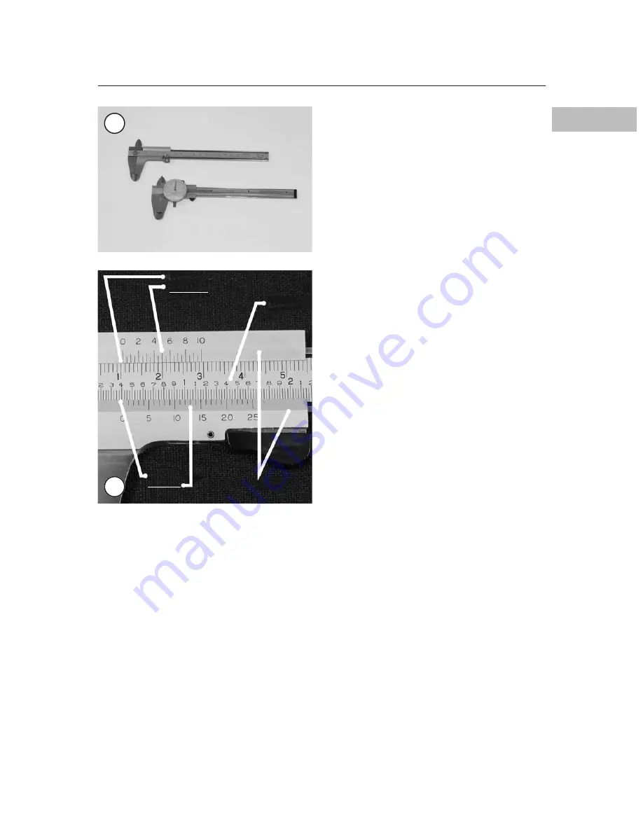
Calipers (
Figure 27
) are excellent tools for ob-
taining inside, outside and depth measurements. Al-
though not as precise as a micrometer, they allow
reasonable precision, typically to within 0.05 mm
(0.001 in.). Most calipers have a range up to 150
mm (6 in.).
Calipers are available in dial, vernier or digital
versions. Dial calipers have a dial, which is easy to
read. Vernier calipers have marked scales that must
be compared to determine the measurement. The
digital caliper uses an LCD display to show the
measurement.
Properly maintain the measuring surfaces of the
caliper. There must not be any dirt or burrs between
the tool and the object being measured. Never force
the caliper closed around an object. Close the cali-
per around the highest point so it can be removed
with a slight drag. Some calipers require calibra-
tion. Always refer to the manufacturer’s instruc-
tions when using a new or unfamiliar caliper.
Figure 28
shows a measurement taken with a
metric vernier caliper. To read the measurement,
note that the fixed scale is graduated in centimeters,
which is indicated by the whole numbers 1, 2, 3 and
so on. Each centimeter is then divided into millime-
ters, which are indicated by the small line between
the whole numbers. (1 centimeter equals 10 milli-
meters). The movable scale is marked in increments
of 0.05 (hundredths) mm. The value of a measure-
ment equals the reading on the fixed scale plus the
reading on the movable scale.
To determine the reading on the fixed scale, look
for the line on the fixed scale immediately to the left
of the 0-line on the movable scale. In
Figure 28
, the
fixed scale reading is 1 centimeter (or 10 millime-
ters).
To determine the reading on the movable scale,
note the one line on the movable scale that precisely
aligns with a line on the fixed scale. Look closely. A
number of lines will seem close, but only one aligns
precisely with a line on the fixed scale. In
Figure
28
, the movable scale reading is 0.50 mm.
To calculate the measurement, add the fixed scale
reading (10 mm) to the movable scale reading (0.50
mm) for a value of 10.50 mm.
GENERAL INFORMATION
15
1
27
28
10.00 mm
0.50 mm
10.50 mm
Moveable scales
Fixed
scale
0.400 in
.
0.013 in.
0.413 in.


