TF5/TF3/TF1
130
6.
Operation method outline
6-1. Operation by GUI of TF main part
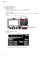
• Starting the test program
A power supply is started pushing
[A]
switch and
[F]
switch of
"USER DEFINED KEYS"
.
After that, wait until the test screen starts.
• How to Basic Operation
By turning the
[TOUCH AND TURN]
knob, the button in a screen is chosen and it performs by pushing the
[TOUCH AND
TURN]
knob.
Or else, select or execute by touching the button on the screen directly.
USER DEFINED KEYS
[TOUCH AND TURN]
knob
[A]
switch
[F]
switch
• The main part GUI operation method
Starting screen
t
y
u
!0
!1
!2
!3
!4
i
o
q
w
e
r
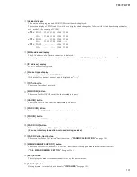
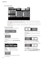
After the test program starts, the above starting screen is displayed.
The checking screen starts by operating pushing a desired inspection button.
Содержание TF5
Страница 10: ...10 TF5 TF3 TF1 866 716 225 599 225 599 TF5 TF3 Unit mm Unit mm DIMENSIONS...
Страница 11: ...11 TF5 TF3 TF1 225 510 599 TF1 Unit mm...
Страница 110: ...B B MAIN MAINCOM Circuit Board 2NA0 ZJ06330 3 110 TF5 TF3 TF1...
Страница 111: ...B B Scale 90 100 Pattern side 2NA0 ZJ06330 3 111 TF5 TF3 TF1...
Страница 112: ...WR 3 1 1 WR 1 WR 0 1 1 WR 36 1 WR 1 DA1 DACOM Circuit Board Component side 2NA ZJ06450 1 112 TF5 TF3 TF1...
Страница 113: ...WR 1 WR 1 DA2 Circuit Board Scale 90 100 Component side 2NA ZJ06430 2 113 TF5 TF3 TF1...
Страница 116: ...WR 1 WR 1 7 WR 32 5 6 C C PS Circuit Board 2NA ZJ06320 2 116 TF5 TF3 TF1...
Страница 119: ...Component side D D Component side 2NA ZJ06380 4 119 TF5 TF3 TF1...
Страница 120: ...7 WR 31 1 7 WR 31 1 7 WR 31 1 WR 31 1 WR 31 1 QRW LQVWDOOHG E E PNC PNCOM Circuit Board 2NA ZJ06380 4 120 TF5 TF3 TF1...
Страница 166: ...TF5 TF3 TF1 166 q w e r PLAY q PASS FAIL w CLOSE USER DEFINED KEYS B...
Страница 201: ...TF5 TF3 TF1 201 USB 1 1GByte USB FAT32 2 1 YSISS TF updater v bin USB root 2 USB TF USB 3 4 LCD Update 5 LCD 6 LCD Close...
Страница 202: ...TF5 TF3 TF1 202 7 SYSTEM SETUP ABOUT 8 HOME Initialize All Memory CANCEL OK OK EXIT...


