20
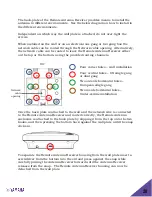
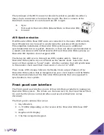
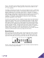
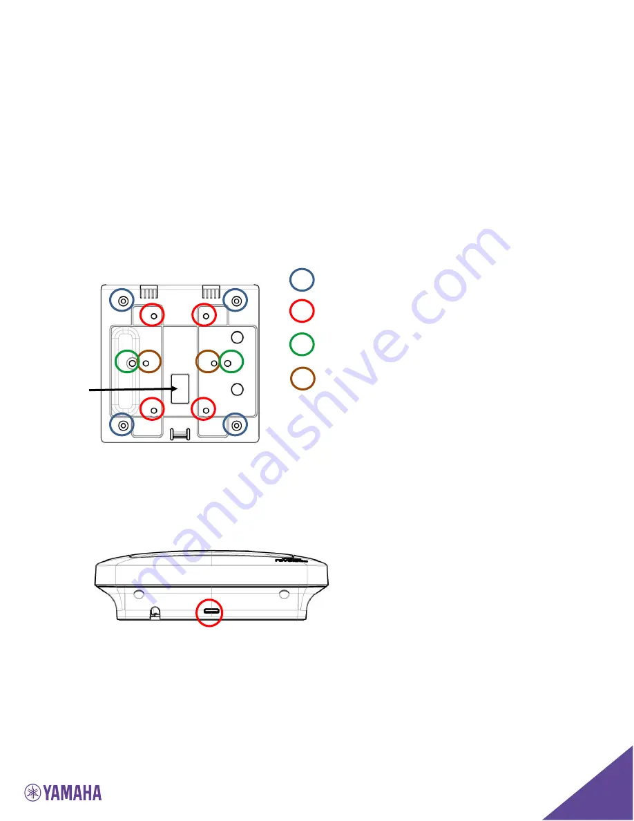
The back-plate of the Remote Antenna Receiver provides means to install the
antenna in different environments. See the below diagram on how to install in
the different environments.
Independent on which way the wall plate is attached, do not over-tight the
screws.
When installed on the wall or on an electrical one gang or two gang box the
network cable can be routed through the Network cable opening. Alternatively,
the network cable can be routed to leave the Remote Antenna Receiver either
on the top or the bottom, using the provided routing channels.
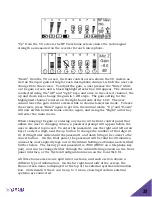
Once the back plate is attached to the wall and the network wire is connected
to the Remote Antenna Receiver and routed correctly, the Remote Antenna
enclosure is attached to the back plate by slipping it from the top onto the two
hooks, and then pressing the bottom back against the wall plate until the snap
clicks in.
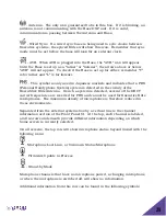
To separate the Remote Antenna Receiver housing from the wall plate insert a
screwdriver from the bottom into the slit and press against the snap while
carefully pulling the Antenna Receiver forward until the Antenna Receiver
releases from the snap. The Remote Antenna Receiver housing can now be
detached from the wall plate.
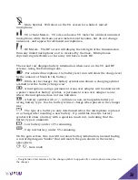
TOP
Four corner holes – wall installation
Four central holes – US single gang
or dual gang
Two outside horizontal holes –
European single gang
Two inside horizontal holes –
Under-ceiling installation
Network
cable
opening

