


88
11
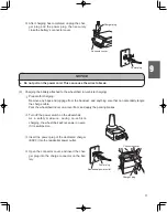
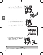
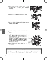
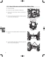
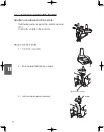
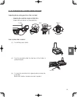
Push in each power unit completely. Check to ensure
that the two balls “a” on the end of the axle can be seen
completely.
White dot
Cap
Connector
(on the cable side)
Connector
(on the wheel side)
a
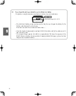
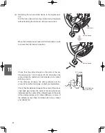
Pull each power unit to ensure that it will not come off.
Place the power units in their normal position, and then
apply the parking brakes.
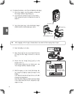
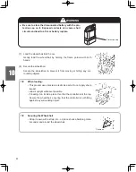
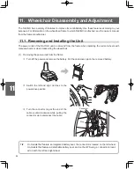
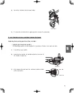
Remove the cap from the connector on the left
wheel.
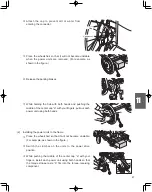
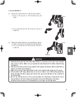
Align the white dot (arrow mark) on the connector
at the end of the cable with the white dot on the
connector on the wheel side, and then push in the
cable connector until it clicks.
Connect the cable with an L mark to the connector
with an L mark (on the wheel side), and connect
the cable with an R mark to the connector with an
R mark (on the wheel side).
Make sure that the connector will not be
disconnected.
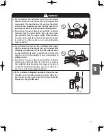
NOTICE
● When you install the right wheel on models that feature an integrated battery, support the
battery storage compartment to prevent the wheel from turning. Otherwise, the wheel might
turn, possibly causing damage to the switch or the battery storage compartment.
White dot
Содержание NAVIGO
Страница 28: ...1 22 1 6 Warning Label Location Diagram Power Unit and Controller NAVIGO 16 FRONT BACK ...
Страница 29: ...1 23 NAVIGO 24 FRONT BACK ...
Страница 30: ...1 24 Lithium Ion Battery Nickel Metal Hydride Battery Back side ...
Страница 31: ...1 25 Charger for Lithium Ion and Nickel Metal Hydride Battery ESC3 ...


