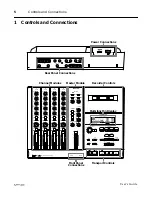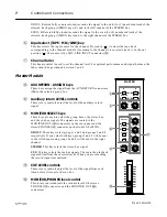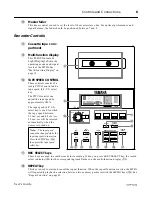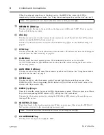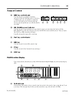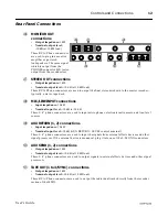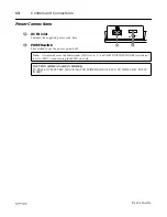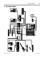
Controls and Connections
6
User’s Guide
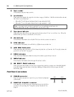
Channel Modules
1
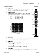
GAIN control
This rotary control adjusts the level of the signal from a microphone or
instrument plugged into the MIC/LINE INPUT connector (
h
).
2
Equalizer controls
These rotary controls are used to adjust the high, middle and low band
frequency levels. To help you select the “flat” setting easily, each control
has a centre-detent at the “0” position.
HIGH
±
12 dB at 12kHz - shelving
MID
±
12 dB at 1kHz - peaking
LOW
±
12 dB at 80Hz - shelving
0
MIC/LINE
1
HIGH
GAIN
MID
LOW
AUX
PAN
1
3
2
4
LINE
MIC
-12
+12
-12
+12
-12
+12
AUX 1
AUX 2
R
EVEN
L
ODD
MIC/
LINE
TAPE
ASSIGN
C
10
9
8
7
6
5
4
3
2
1
0
0
0
0
2
4
7
6
5
3
1
10k
20k
1k
100
20
–15
–10
–5
0
5
10
15
FREQUENCY (Hz)
RESPONSE (dB)
50
5k
2k
500
200
3
AUX controls
This rotary control is used to send the channel signal after the fader (
7
) to the auxiliary send buses.
Rotated fully counter-clockwise sends the signal to the AUX 1 bus, fully clockwise to the AUX 2 bus.
In the centre-detent “0” position, no signal is sent to either bus.
4
ASSIGN keys
These keys are used to select the group bus.
1-ASSIGN-2
selects the first track group - groups 1 and 2.
3-ASSIGN-4
selects the second track group - groups 3 and 4.
Use the PAN control (
5
) to select the individual track groups.
5
PAN control
This rotary control sets the stereo pan position of the channel signal. It is also used to select the
individual track groups for recording.
1
2
3
4

