REAR BRAKE
4-53
• Never use solvents on internal brake com-
ponents as they will cause the brake caliper
piston dust seal and brake caliper piston
seal to swell and distort.
• Whenever a brake caliper is disassembled,
replace the brake caliper piston dust seal
and brake caliper piston seal.
EAS22670
INSTALLING THE REAR BRAKE CALIPER
1. Install:
• Rear brake caliper assembly
(temporarily)
• Rear wheel axle
• Brake torque rod
• Rear wheel axle nut
TIP
• Do not install the brake pads, brake pad shims,
and brake pad springs.
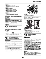
• Align the slot “a” of the rear wheel sensor hous-
ing “1” with the projection “b” of the rear brake
caliper bracket “2”, and then assemble them.
• After assembling the rear wheel sensor hous-
ing and the rear brake caliper bracket, make
sure that the projection “c” on the housing is
aligned with the projection “d” on the bracket.
NOTICE
ECA14470
Make sure there are no foreign materials in
the wheel hub. Foreign materials cause dam-
age to the inner sensor rotor and wheel sen-
sor.
WARNING
EWA13500
Make sure the brake hose is routed properly.
2. Tighten:
• Brake torque rod nuts
• Rear wheel axle nut
• Rear wheel axle pinch bolt
3. Install:
• Copper washers
• Brake hose (proportioning valve to rear brake
caliper) “1”
• Brake hose union bolt “2”
WARNING
EW3P66002
Proper brake hose routing is essential to in-
sure safe vehicle operation. Refer to “CABLE
ROUTING (FJR13A)” on page 2-45 and “CA-
BLE ROUTING (FJR13AE)” on page 2-65.
NOTICE
EC3P61044
When installing the brake hose onto the
brake caliper, make sure the brake pipe “a”
touches the projection “b” on the brake cali-
per.
Recommended fluid
DOT 4
T
R
.
.
Brake torque rod nut
30 Nm (3.0 m·kg, 22 ft·lb)
Rear wheel axle nut
125 Nm (12.5 m·kg, 90 ft·lb)
Rear wheel axle pinch bolt
23 Nm (2.3 m·kg, 17 ft·lb)
T
R
.
.
Brake hose union bolt
30 Nm (3.0 m·kg, 22 ft·lb)
New
1
2
a
b
Содержание FJR13AY 2009
Страница 1: ...2009 SERVICE MANUAL FJR13AY C FJR13AEY C LIT 11616 22 73 3P6 28197 12 ...
Страница 6: ......
Страница 8: ......
Страница 80: ...LUBRICATION SYSTEM CHART AND DIAGRAMS 2 31 EAS20410 LUBRICATION DIAGRAMS 5 6 7 1 2 3 4 ...
Страница 82: ...LUBRICATION SYSTEM CHART AND DIAGRAMS 2 33 1 3 2 ...
Страница 83: ...LUBRICATION SYSTEM CHART AND DIAGRAMS 2 34 1 Main axle 2 Drive axle 3 Oil delivery pipe 1 ...
Страница 84: ...LUBRICATION SYSTEM CHART AND DIAGRAMS 2 35 6 5 4 3 2 1 ...
Страница 86: ...LUBRICATION SYSTEM CHART AND DIAGRAMS 2 37 1 2 3 4 5 6 7 8 9 ...
Страница 88: ...LUBRICATION SYSTEM CHART AND DIAGRAMS 2 39 4 5 3 2 1 9 8 6 7 ...
Страница 92: ...COOLING SYSTEM DIAGRAMS 2 43 A A 7 1 2 3 4 5 5 7 8 6 8 9 10 11 12 ...
Страница 98: ...CABLE ROUTING FJR13A 2 49 2 3 4 5 6 7 8 9 11 10 12 13 14 15 16 A B C D E F 1 1 ...
Страница 100: ...CABLE ROUTING FJR13A 2 51 1 2 3 4 5 6 7 8 A B C D E 9 10 11 12 13 ...
Страница 108: ...CABLE ROUTING FJR13A 2 59 1 2 3 4 A B B C D E ...
Страница 110: ...CABLE ROUTING FJR13A 2 61 A 1 A A B P O C D E F G H I J K L M N 2 3 4 5 6 7 8 9 10 A 11 ...
Страница 118: ...CABLE ROUTING FJR13AE 2 69 2 3 4 5 6 7 8 9 11 12 13 14 15 16 17 A B C E D F 1 1 H 10 18 G ...
Страница 120: ...CABLE ROUTING FJR13AE 2 71 1 2 3 4 5 6 7 8 A B C D E 9 10 11 12 13 ...
Страница 128: ...CABLE ROUTING FJR13AE 2 79 1 4 2 5 6 A B C D D E 3 F G ...
Страница 130: ...CABLE ROUTING FJR13AE 2 81 A 1 A A B P O C D E F G H I J K L M N 2 3 4 5 6 7 8 9 10 A 11 ...
Страница 134: ...CABLE ROUTING FJR13AE 2 85 ...
Страница 137: ......
Страница 196: ...GENERAL CHASSIS 4 11 b a 1 2 ...
Страница 302: ...SHAFT DRIVE 4 117 ...
Страница 317: ...ENGINE REMOVAL 5 12 3 Check Gear position setting Refer to Diagnostic code table Diagnostic code No Sh_ _65 1 2 3 ...
Страница 326: ...CAMSHAFTS 5 21 ...
Страница 424: ...CONNECTING RODS AND PISTONS 5 119 ...
Страница 462: ...WATER PUMP 6 15 ...
Страница 473: ...THROTTLE BODIES 7 10 ...
Страница 474: ...AIR INDUCTION SYSTEM 7 11 EAS27040 AIR INDUCTION SYSTEM 1 2 3 4 5 1 1 1 1 2 2 5 2 3 3 4 7 8 6 ...
Страница 483: ......
Страница 495: ...IGNITION SYSTEM 8 12 ...
Страница 511: ...ELECTRIC STARTING SYSTEM 8 28 ...
Страница 513: ...CHARGING SYSTEM 8 30 2 Rectifier regulator 3 AC magneto 8 Main fuse 10 Battery ...
Страница 515: ...CHARGING SYSTEM 8 32 ...
Страница 539: ...COOLING SYSTEM 8 56 ...
Страница 587: ...FUEL PUMP SYSTEM 8 104 ...
Страница 597: ...ACCESSORY BOX SYSTEM 8 114 52 Coupler 4 wire harness front cowling wire harness 77 Accessory box solenoid ...
Страница 599: ...ACCESSORY BOX SYSTEM 8 116 ...
Страница 609: ...ABS ANTI LOCK BRAKE SYSTEM 8 126 ...
Страница 696: ...ELECTRICAL COMPONENTS 8 213 EAS27970 ELECTRICAL COMPONENTS FJR13A 1 18 2 3 4 5 6 7 8 9 10 11 12 13 14 15 16 17 ...
Страница 698: ...ELECTRICAL COMPONENTS 8 215 FJR13A 5 1 3 2 17 8 10 11 12 13 14 15 16 7 6 4 9 ...
Страница 700: ...ELECTRICAL COMPONENTS 8 217 FJR13AE 13 16 18 17 2 3 4 5 6 7 8 1 9 10 11 12 15 14 19 ...
Страница 702: ...ELECTRICAL COMPONENTS 8 219 FJR13AE 1 19 3 2 5 7 9 8 12 13 14 15 16 11 10 18 17 6 4 ...
Страница 730: ...ELECTRICAL COMPONENTS 8 247 ...
Страница 738: ...W L White Blue W Y White Yellow Y B Yellow Black Y G Yellow Green Y L Yellow Blue Y R Yellow Red Y W Yellow White ...
Страница 739: ......
Страница 740: ...YAMAHA MOTOR CO LTD 2500 SHINGAI IWATA SHIZUOKA JAPAN ...


