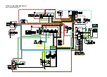
ET3P66050
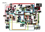
WIRING DIAGRAM
FJR13AEY(C) 2009
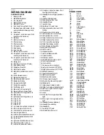
1. Main switch
2. Rectifier/regulator
3. AC magneto
4. ABS solenoid fuse
5. ABS ECU fuse
6. Fuel injection system fuse
7. Backup fuse (odometer, clock,
and windshield drive system)
8. Main fuse
9. Battery
10. ABS motor fuse
11. Starter relay
12. Starter motor
13. Coupler 1 (wire harness–front
cowling wire harness)
14. Coupler 2 (wire harness–front
cowling wire harness)
15. Fuel pump
16. Fuel sender
17. Oil level switch
18. Relay unit
19. Starting circuit cut-off relay
20. Fuel pump relay
21. Neutral switch
22. ABS test coupler
23. ABS ECU (electronic control
unit)
24. Front wheel sensor
25. Rear wheel sensor
26. Coupler 3 (wire harness–front
cowling wire harness)
27. Diode
28. Brake light relay
29. Rear brake light switch
30. License plate light
31. Taillight assembly
32. Tail/brake light
33. Rear left turn signal light
34. Rear right turn signal light
35. Sidestand switch
36. Cylinders-#1/#4 ignition coil
37. Spark plug
38. Cylinders-#2/#3 ignition coil
39. Injector #4
40. Injector #3
41. Injector #2
42. Injector #1
43. Air induction system solenoid
44. ECU (engine control unit)
45. Crankshaft position sensor
46. Intake air temperature sensor
47. Coolant temperature sensor
48. Lean angle sensor
49. O
2
sensor
50. Cylinder identification sensor
51. Throttle position sensor
52. Intake air pressure sensor
53. Shift actuator motor
54. Shift actuator sensor
55. Clutch actuator sensor
56. Clutch actuator motor
57. MCU (motor control unit)
58. YCC-S test coupler
59. Coupler 4 (wire harness–front
cowling wire harness)
60. Foot shift switch
61. YCC-S speed sensor
62. Gear position sensor
63. YCC-S control relay
64. Coupler 5 (wire harness–front
cowling wire harness)
65. Headlight (on/off)/grip warmer
relay
66. Coupler 6 (wire harness–front
cowling wire harness)
67. Hazard lighting fuse
68. Signaling system fuse
69. Headlight fuse
70. Ignition fuse
71. Auxiliary DC jack fuse
72. Grip warmer control unit
73. Radiator fan motor relay
74. Left radiator fan motor fuse
75. Left radiator fan motor
76. Right radiator fan motor fuse
77. Right radiator fan motor
78. YCC-S motor control fuse
79. Turn signal/hazard relay
80. Left handlebar switch
81. Dimmer switch
82. Windshield position switch
83. Turn signal switch
84. Horn switch
85. Right handlebar switch
86. Front brake light switch
87. Engine stop switch
88. Start switch
89. Hazard switch
90. Accessory box solenoid
91. Meter assembly
92. Neutral indicator light
93. ABS warning light
94. Multi-function meter
95. Oil level warning light
96. Engine trouble warning light
97. Meter light
98. High beam indicator light
99. Right turn signal indicator light
100.Left turn signal indicator light
101.Thermistor
102.Hand shift switch
103.Hand shift lever switch (shift
up)
104.Hand shift lever switch (shift
down)
105.Hand shift select button
106.Hand shift select indicator light
107.Horn
108.Front left turn signal/position
light
109.Front right turn signal/position
light
110.Headlight assembly
111.Headlight
112.Headlight relay (dimmer)
113.Windshield drive unit
114.Left grip warmer
115.Right grip warmer
116.Auxiliary DC jack
ET3P66066
COLOR CODE
B
Black
Br
Brown
Ch
Chocolate
Dg
Dark green
G
Green
Gy
Gray
L
Blue
Lg
Light green
O
Orange
P
Pink
R
Red
Sb
Sky blue
W
White
Y
Yellow
B/G
Black/Green
B/L
Black/Blue
B/R
Black/Red
B/W
Black/White
B/Y
Black/Yellow
Br/B
Brown/Black
Br/G
Brown/Green
Br/L
Brown/Blue
Br/R
Brown/Red
Br/W
Brown/White
Br/Y
Brown/Yellow
G/B
Green/Black
G/L
Green/Blue
G/R
Green/Red
G/W
Green/White
G/Y
Green/Yellow
Gy/R
Gray/Red
Gy/W
Gray/White
L/B
Blue/Black
L/G
Blue/Green
L/R
Blue/Red
L/W
Blue/White
L/Y
Blue/Yellow
Lg/W
Light green/White
O/B Orange/Black
O/G
Orange/Green
O/R
Orange/Red
O/W
Orange/White
P/W
Pink/White
R/B
Red/Black
R/G
Red/Green
R/L
Red/Blue
R/W
Red/White
R/Y
Red/Yellow
Sb/W
Sky blue/White
W/B
White/Black
Содержание FJR13AY 2009
Страница 1: ...2009 SERVICE MANUAL FJR13AY C FJR13AEY C LIT 11616 22 73 3P6 28197 12 ...
Страница 6: ......
Страница 8: ......
Страница 80: ...LUBRICATION SYSTEM CHART AND DIAGRAMS 2 31 EAS20410 LUBRICATION DIAGRAMS 5 6 7 1 2 3 4 ...
Страница 82: ...LUBRICATION SYSTEM CHART AND DIAGRAMS 2 33 1 3 2 ...
Страница 83: ...LUBRICATION SYSTEM CHART AND DIAGRAMS 2 34 1 Main axle 2 Drive axle 3 Oil delivery pipe 1 ...
Страница 84: ...LUBRICATION SYSTEM CHART AND DIAGRAMS 2 35 6 5 4 3 2 1 ...
Страница 86: ...LUBRICATION SYSTEM CHART AND DIAGRAMS 2 37 1 2 3 4 5 6 7 8 9 ...
Страница 88: ...LUBRICATION SYSTEM CHART AND DIAGRAMS 2 39 4 5 3 2 1 9 8 6 7 ...
Страница 92: ...COOLING SYSTEM DIAGRAMS 2 43 A A 7 1 2 3 4 5 5 7 8 6 8 9 10 11 12 ...
Страница 98: ...CABLE ROUTING FJR13A 2 49 2 3 4 5 6 7 8 9 11 10 12 13 14 15 16 A B C D E F 1 1 ...
Страница 100: ...CABLE ROUTING FJR13A 2 51 1 2 3 4 5 6 7 8 A B C D E 9 10 11 12 13 ...
Страница 108: ...CABLE ROUTING FJR13A 2 59 1 2 3 4 A B B C D E ...
Страница 110: ...CABLE ROUTING FJR13A 2 61 A 1 A A B P O C D E F G H I J K L M N 2 3 4 5 6 7 8 9 10 A 11 ...
Страница 118: ...CABLE ROUTING FJR13AE 2 69 2 3 4 5 6 7 8 9 11 12 13 14 15 16 17 A B C E D F 1 1 H 10 18 G ...
Страница 120: ...CABLE ROUTING FJR13AE 2 71 1 2 3 4 5 6 7 8 A B C D E 9 10 11 12 13 ...
Страница 128: ...CABLE ROUTING FJR13AE 2 79 1 4 2 5 6 A B C D D E 3 F G ...
Страница 130: ...CABLE ROUTING FJR13AE 2 81 A 1 A A B P O C D E F G H I J K L M N 2 3 4 5 6 7 8 9 10 A 11 ...
Страница 134: ...CABLE ROUTING FJR13AE 2 85 ...
Страница 137: ......
Страница 196: ...GENERAL CHASSIS 4 11 b a 1 2 ...
Страница 302: ...SHAFT DRIVE 4 117 ...
Страница 317: ...ENGINE REMOVAL 5 12 3 Check Gear position setting Refer to Diagnostic code table Diagnostic code No Sh_ _65 1 2 3 ...
Страница 326: ...CAMSHAFTS 5 21 ...
Страница 424: ...CONNECTING RODS AND PISTONS 5 119 ...
Страница 462: ...WATER PUMP 6 15 ...
Страница 473: ...THROTTLE BODIES 7 10 ...
Страница 474: ...AIR INDUCTION SYSTEM 7 11 EAS27040 AIR INDUCTION SYSTEM 1 2 3 4 5 1 1 1 1 2 2 5 2 3 3 4 7 8 6 ...
Страница 483: ......
Страница 495: ...IGNITION SYSTEM 8 12 ...
Страница 511: ...ELECTRIC STARTING SYSTEM 8 28 ...
Страница 513: ...CHARGING SYSTEM 8 30 2 Rectifier regulator 3 AC magneto 8 Main fuse 10 Battery ...
Страница 515: ...CHARGING SYSTEM 8 32 ...
Страница 539: ...COOLING SYSTEM 8 56 ...
Страница 587: ...FUEL PUMP SYSTEM 8 104 ...
Страница 597: ...ACCESSORY BOX SYSTEM 8 114 52 Coupler 4 wire harness front cowling wire harness 77 Accessory box solenoid ...
Страница 599: ...ACCESSORY BOX SYSTEM 8 116 ...
Страница 609: ...ABS ANTI LOCK BRAKE SYSTEM 8 126 ...
Страница 696: ...ELECTRICAL COMPONENTS 8 213 EAS27970 ELECTRICAL COMPONENTS FJR13A 1 18 2 3 4 5 6 7 8 9 10 11 12 13 14 15 16 17 ...
Страница 698: ...ELECTRICAL COMPONENTS 8 215 FJR13A 5 1 3 2 17 8 10 11 12 13 14 15 16 7 6 4 9 ...
Страница 700: ...ELECTRICAL COMPONENTS 8 217 FJR13AE 13 16 18 17 2 3 4 5 6 7 8 1 9 10 11 12 15 14 19 ...
Страница 702: ...ELECTRICAL COMPONENTS 8 219 FJR13AE 1 19 3 2 5 7 9 8 12 13 14 15 16 11 10 18 17 6 4 ...
Страница 730: ...ELECTRICAL COMPONENTS 8 247 ...
Страница 738: ...W L White Blue W Y White Yellow Y B Yellow Black Y G Yellow Green Y L Yellow Blue Y R Yellow Red Y W Yellow White ...
Страница 739: ......
Страница 740: ...YAMAHA MOTOR CO LTD 2500 SHINGAI IWATA SHIZUOKA JAPAN ...


