FUEL INJECTION SYSTEM
8-75
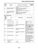
*1 If it is not possible to check the intake temperature, use the ambient temperature as reference (use
the compared values for reference).
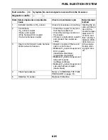
Actuator operation table
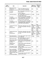
d:62
Malfunction history code
erasure
• No history
0
—
• History exists
• Displays the total number of
malfunctions, including the
current malfunction, that
have occurred since the
history was last erased.
(For example, if there have
been three malfunctions,
“03” is displayed.)
To erase the history, set the
engine stop switch from
“
” to “
”.
d:70
Control number
0–255
—
Diag-
nostic
code
No.
Item
Meter display
Checking method
Diag-
nostic
code
No.
Item
Actuation
Checking method
d:30
Cylinders-#1/#4 ignition
coil
Actuates the cylinders-#1/#4
ignition coil five times at one-
second intervals.
Illuminates the engine trou-
ble warning light.
Check the spark five times.
• Connect an ignition
checker.
d:31
Cylinders-#2/#3 ignition
coil
Actuates the cylinders-#2/#3
ignition coil five times at one-
second intervals.
Illuminates the engine trou-
ble warning light.
Check the spark five times.
• Connect an ignition
checker.
d:36
Injector #1
Actuates the injector #1 five
times at one-second inter-
vals.
Illuminates the engine trou-
ble warning light.
Check the operating sound
of the injector #1 five times.
d:37
Injector #2
Actuates the injector #2 five
times at one-second inter-
vals.
Illuminates the engine trou-
ble warning light.
Check the operating sound
of the injector #2 five times.
d:38
Injector #3
Actuates the injector #3 five
times at one-second inter-
vals.
Illuminates the engine trou-
ble warning light.
Check the operating sound
of the injector #3 five times.
Содержание FJR13AY 2009
Страница 1: ...2009 SERVICE MANUAL FJR13AY C FJR13AEY C LIT 11616 22 73 3P6 28197 12 ...
Страница 6: ......
Страница 8: ......
Страница 80: ...LUBRICATION SYSTEM CHART AND DIAGRAMS 2 31 EAS20410 LUBRICATION DIAGRAMS 5 6 7 1 2 3 4 ...
Страница 82: ...LUBRICATION SYSTEM CHART AND DIAGRAMS 2 33 1 3 2 ...
Страница 83: ...LUBRICATION SYSTEM CHART AND DIAGRAMS 2 34 1 Main axle 2 Drive axle 3 Oil delivery pipe 1 ...
Страница 84: ...LUBRICATION SYSTEM CHART AND DIAGRAMS 2 35 6 5 4 3 2 1 ...
Страница 86: ...LUBRICATION SYSTEM CHART AND DIAGRAMS 2 37 1 2 3 4 5 6 7 8 9 ...
Страница 88: ...LUBRICATION SYSTEM CHART AND DIAGRAMS 2 39 4 5 3 2 1 9 8 6 7 ...
Страница 92: ...COOLING SYSTEM DIAGRAMS 2 43 A A 7 1 2 3 4 5 5 7 8 6 8 9 10 11 12 ...
Страница 98: ...CABLE ROUTING FJR13A 2 49 2 3 4 5 6 7 8 9 11 10 12 13 14 15 16 A B C D E F 1 1 ...
Страница 100: ...CABLE ROUTING FJR13A 2 51 1 2 3 4 5 6 7 8 A B C D E 9 10 11 12 13 ...
Страница 108: ...CABLE ROUTING FJR13A 2 59 1 2 3 4 A B B C D E ...
Страница 110: ...CABLE ROUTING FJR13A 2 61 A 1 A A B P O C D E F G H I J K L M N 2 3 4 5 6 7 8 9 10 A 11 ...
Страница 118: ...CABLE ROUTING FJR13AE 2 69 2 3 4 5 6 7 8 9 11 12 13 14 15 16 17 A B C E D F 1 1 H 10 18 G ...
Страница 120: ...CABLE ROUTING FJR13AE 2 71 1 2 3 4 5 6 7 8 A B C D E 9 10 11 12 13 ...
Страница 128: ...CABLE ROUTING FJR13AE 2 79 1 4 2 5 6 A B C D D E 3 F G ...
Страница 130: ...CABLE ROUTING FJR13AE 2 81 A 1 A A B P O C D E F G H I J K L M N 2 3 4 5 6 7 8 9 10 A 11 ...
Страница 134: ...CABLE ROUTING FJR13AE 2 85 ...
Страница 137: ......
Страница 196: ...GENERAL CHASSIS 4 11 b a 1 2 ...
Страница 302: ...SHAFT DRIVE 4 117 ...
Страница 317: ...ENGINE REMOVAL 5 12 3 Check Gear position setting Refer to Diagnostic code table Diagnostic code No Sh_ _65 1 2 3 ...
Страница 326: ...CAMSHAFTS 5 21 ...
Страница 424: ...CONNECTING RODS AND PISTONS 5 119 ...
Страница 462: ...WATER PUMP 6 15 ...
Страница 473: ...THROTTLE BODIES 7 10 ...
Страница 474: ...AIR INDUCTION SYSTEM 7 11 EAS27040 AIR INDUCTION SYSTEM 1 2 3 4 5 1 1 1 1 2 2 5 2 3 3 4 7 8 6 ...
Страница 483: ......
Страница 495: ...IGNITION SYSTEM 8 12 ...
Страница 511: ...ELECTRIC STARTING SYSTEM 8 28 ...
Страница 513: ...CHARGING SYSTEM 8 30 2 Rectifier regulator 3 AC magneto 8 Main fuse 10 Battery ...
Страница 515: ...CHARGING SYSTEM 8 32 ...
Страница 539: ...COOLING SYSTEM 8 56 ...
Страница 587: ...FUEL PUMP SYSTEM 8 104 ...
Страница 597: ...ACCESSORY BOX SYSTEM 8 114 52 Coupler 4 wire harness front cowling wire harness 77 Accessory box solenoid ...
Страница 599: ...ACCESSORY BOX SYSTEM 8 116 ...
Страница 609: ...ABS ANTI LOCK BRAKE SYSTEM 8 126 ...
Страница 696: ...ELECTRICAL COMPONENTS 8 213 EAS27970 ELECTRICAL COMPONENTS FJR13A 1 18 2 3 4 5 6 7 8 9 10 11 12 13 14 15 16 17 ...
Страница 698: ...ELECTRICAL COMPONENTS 8 215 FJR13A 5 1 3 2 17 8 10 11 12 13 14 15 16 7 6 4 9 ...
Страница 700: ...ELECTRICAL COMPONENTS 8 217 FJR13AE 13 16 18 17 2 3 4 5 6 7 8 1 9 10 11 12 15 14 19 ...
Страница 702: ...ELECTRICAL COMPONENTS 8 219 FJR13AE 1 19 3 2 5 7 9 8 12 13 14 15 16 11 10 18 17 6 4 ...
Страница 730: ...ELECTRICAL COMPONENTS 8 247 ...
Страница 738: ...W L White Blue W Y White Yellow Y B Yellow Black Y G Yellow Green Y L Yellow Blue Y R Yellow Red Y W Yellow White ...
Страница 739: ......
Страница 740: ...YAMAHA MOTOR CO LTD 2500 SHINGAI IWATA SHIZUOKA JAPAN ...


