CLUTCH
5-63
EAS25170
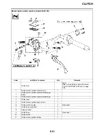
CHECKING THE PRESSURE PLATE
1. Check:
• Pressure plate
Cracks/damage
→
Replace.
• Bearing
Damage/wear
→
Replace.
EAS25190
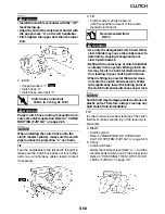
CHECKING THE CLUTCH PUSH RODS
1. Check:
• O-ring
• Short clutch push rod
• Long clutch push rod
• Ball
Cracks/damage/wear
→
Replace the defec-
tive part(s).
2. Measure:
• Long clutch push rod bending limit
Out of specification
→
Replace the long
clutch push rod.
EAS25210
CHECKING THE PRIMARY DRIVEN GEAR
1. Check:
• Primary driven gear “1”
Damage/wear
→
Replace the primary drive
and primary driven gears as a set.
Excessive noise during operation
→
Replace
the clutch housing and crankshaft as a set.
EAS25250
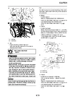
INSTALLING THE CLUTCH (FJR13A)
1. Install:
• Clutch housing “1”
TIP
• Make sure that the projections “a” in the clutch
housing align with the slots “b” in the oil pump
drive sprocket.
• Make sure that the primary driven gear teeth
and primary drive gear teeth mesh correctly.
• Insert a cross-headed screwdriver into one of
the holes of the clutch housing and primary
driven gear, and then rotate the inner primary
driven gear until both primary drive gears are
aligned. The teeth of both primary driven gears
must be aligned for installation.
2. Install:
• Spacer “1”
TIP
Install the spacer with the two screw holes facing
towards the clutch boss.
Long clutch push rod bending
limit
0.37 mm (0.015 in)
Содержание FJR13AY 2009
Страница 1: ...2009 SERVICE MANUAL FJR13AY C FJR13AEY C LIT 11616 22 73 3P6 28197 12 ...
Страница 6: ......
Страница 8: ......
Страница 80: ...LUBRICATION SYSTEM CHART AND DIAGRAMS 2 31 EAS20410 LUBRICATION DIAGRAMS 5 6 7 1 2 3 4 ...
Страница 82: ...LUBRICATION SYSTEM CHART AND DIAGRAMS 2 33 1 3 2 ...
Страница 83: ...LUBRICATION SYSTEM CHART AND DIAGRAMS 2 34 1 Main axle 2 Drive axle 3 Oil delivery pipe 1 ...
Страница 84: ...LUBRICATION SYSTEM CHART AND DIAGRAMS 2 35 6 5 4 3 2 1 ...
Страница 86: ...LUBRICATION SYSTEM CHART AND DIAGRAMS 2 37 1 2 3 4 5 6 7 8 9 ...
Страница 88: ...LUBRICATION SYSTEM CHART AND DIAGRAMS 2 39 4 5 3 2 1 9 8 6 7 ...
Страница 92: ...COOLING SYSTEM DIAGRAMS 2 43 A A 7 1 2 3 4 5 5 7 8 6 8 9 10 11 12 ...
Страница 98: ...CABLE ROUTING FJR13A 2 49 2 3 4 5 6 7 8 9 11 10 12 13 14 15 16 A B C D E F 1 1 ...
Страница 100: ...CABLE ROUTING FJR13A 2 51 1 2 3 4 5 6 7 8 A B C D E 9 10 11 12 13 ...
Страница 108: ...CABLE ROUTING FJR13A 2 59 1 2 3 4 A B B C D E ...
Страница 110: ...CABLE ROUTING FJR13A 2 61 A 1 A A B P O C D E F G H I J K L M N 2 3 4 5 6 7 8 9 10 A 11 ...
Страница 118: ...CABLE ROUTING FJR13AE 2 69 2 3 4 5 6 7 8 9 11 12 13 14 15 16 17 A B C E D F 1 1 H 10 18 G ...
Страница 120: ...CABLE ROUTING FJR13AE 2 71 1 2 3 4 5 6 7 8 A B C D E 9 10 11 12 13 ...
Страница 128: ...CABLE ROUTING FJR13AE 2 79 1 4 2 5 6 A B C D D E 3 F G ...
Страница 130: ...CABLE ROUTING FJR13AE 2 81 A 1 A A B P O C D E F G H I J K L M N 2 3 4 5 6 7 8 9 10 A 11 ...
Страница 134: ...CABLE ROUTING FJR13AE 2 85 ...
Страница 137: ......
Страница 196: ...GENERAL CHASSIS 4 11 b a 1 2 ...
Страница 302: ...SHAFT DRIVE 4 117 ...
Страница 317: ...ENGINE REMOVAL 5 12 3 Check Gear position setting Refer to Diagnostic code table Diagnostic code No Sh_ _65 1 2 3 ...
Страница 326: ...CAMSHAFTS 5 21 ...
Страница 424: ...CONNECTING RODS AND PISTONS 5 119 ...
Страница 462: ...WATER PUMP 6 15 ...
Страница 473: ...THROTTLE BODIES 7 10 ...
Страница 474: ...AIR INDUCTION SYSTEM 7 11 EAS27040 AIR INDUCTION SYSTEM 1 2 3 4 5 1 1 1 1 2 2 5 2 3 3 4 7 8 6 ...
Страница 483: ......
Страница 495: ...IGNITION SYSTEM 8 12 ...
Страница 511: ...ELECTRIC STARTING SYSTEM 8 28 ...
Страница 513: ...CHARGING SYSTEM 8 30 2 Rectifier regulator 3 AC magneto 8 Main fuse 10 Battery ...
Страница 515: ...CHARGING SYSTEM 8 32 ...
Страница 539: ...COOLING SYSTEM 8 56 ...
Страница 587: ...FUEL PUMP SYSTEM 8 104 ...
Страница 597: ...ACCESSORY BOX SYSTEM 8 114 52 Coupler 4 wire harness front cowling wire harness 77 Accessory box solenoid ...
Страница 599: ...ACCESSORY BOX SYSTEM 8 116 ...
Страница 609: ...ABS ANTI LOCK BRAKE SYSTEM 8 126 ...
Страница 696: ...ELECTRICAL COMPONENTS 8 213 EAS27970 ELECTRICAL COMPONENTS FJR13A 1 18 2 3 4 5 6 7 8 9 10 11 12 13 14 15 16 17 ...
Страница 698: ...ELECTRICAL COMPONENTS 8 215 FJR13A 5 1 3 2 17 8 10 11 12 13 14 15 16 7 6 4 9 ...
Страница 700: ...ELECTRICAL COMPONENTS 8 217 FJR13AE 13 16 18 17 2 3 4 5 6 7 8 1 9 10 11 12 15 14 19 ...
Страница 702: ...ELECTRICAL COMPONENTS 8 219 FJR13AE 1 19 3 2 5 7 9 8 12 13 14 15 16 11 10 18 17 6 4 ...
Страница 730: ...ELECTRICAL COMPONENTS 8 247 ...
Страница 738: ...W L White Blue W Y White Yellow Y B Yellow Black Y G Yellow Green Y L Yellow Blue Y R Yellow Red Y W Yellow White ...
Страница 739: ......
Страница 740: ...YAMAHA MOTOR CO LTD 2500 SHINGAI IWATA SHIZUOKA JAPAN ...


