


GRIP WARMER SYSTEM
8-163
ET3P66019
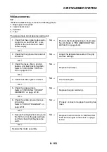
TROUBLESHOOTING
TIP
• Before troubleshooting, remove the following part(s):
1. Right upper inner panel
2. Lower center cover
3. Fuel tank
4. T-bar
The grip warmers do not become warm at all.
NG
→
OK
↓
NG
→
OK
↓
NG
→
OK
↓
NG
→
OK
↓
NG
→
OK
↓
NG
→
OK
↓
NG
→
OK
↓
1. Check that the engine trouble warn-
ing light is on and that “Err” is dis-
played in the multi-function meter
center display.
Perform the troubleshooting for fault code
No. 89. Refer to “TROUBLESHOOTING
DETAILS” on page 8-40.
2. Check that the grip warmers are not
turned off.
Adjust the temperature levels of the grip
warmer settings.
3. Check the fuses. (Main, ignition,
backup, and fuel injection system)
Refer to “CHECKING THE FUS-
ES” on page 8-173.
Replace the fuse(s).
4. Check that the engine is started.
Start the engine.
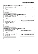
5. Check the grip warmers.
Refer to “CHECKING THE GRIP
WARMERS” on page 8-193.
Replace the grip warmer(s).
6. Check the entire grip warmer sys-
tem wiring.
Refer to “CIRCUIT DIAGRAM” on
page 8-161.
Properly connect or replace the wiring har-
ness.
7. Execute the diagnostic mode (code
No. 57) to turn on the grip warmers,
and then check that they become
warm.
Replace the ECU. Refer to “REPLACING
THE ECU (engine control unit)” on page
8-174.
Replace the meter assembly.
Содержание FJR1300A(D)
Страница 1: ...2013 SERVICE MANUAL FJR1300A D 1MC 28197 E0 ...
Страница 6: ......
Страница 8: ......
Страница 70: ...SPECIAL TOOLS 1 61 ...
Страница 101: ...LUBRICATION POINTS AND LUBRICANT TYPES 2 30 ...
Страница 104: ...LUBRICATION SYSTEM CHART AND DIAGRAMS 2 33 EAS20410 LUBRICATION DIAGRAMS 5 6 7 1 2 3 4 ...
Страница 106: ...LUBRICATION SYSTEM CHART AND DIAGRAMS 2 35 1 3 2 ...
Страница 107: ...LUBRICATION SYSTEM CHART AND DIAGRAMS 2 36 1 Main axle 2 Drive axle 3 Oil delivery pipe 1 ...
Страница 108: ...LUBRICATION SYSTEM CHART AND DIAGRAMS 2 37 6 5 4 3 2 1 ...
Страница 110: ...LUBRICATION SYSTEM CHART AND DIAGRAMS 2 39 1 2 3 4 5 6 7 8 9 ...
Страница 112: ...LUBRICATION SYSTEM CHART AND DIAGRAMS 2 41 4 5 3 2 1 9 8 6 7 ...
Страница 114: ...COOLING SYSTEM DIAGRAMS 2 43 EAS20420 COOLING SYSTEM DIAGRAMS 3 13 4 5 6 7 7 7 8 1 2 10 9 14 15 16 17 11 12 3 ...
Страница 116: ...COOLING SYSTEM DIAGRAMS 2 45 7 1 2 3 4 5 5 8 9 6 8 9 10 11 12 ...
Страница 122: ...CABLE ROUTING 2 51 Rear brake hose right side view 4 5 6 7 8 9 10 11 1 12 13 14 15 2 3 16 1 A B C F E D ...
Страница 124: ...CABLE ROUTING 2 53 Horn and radiator left side view A B 1 1 2 3 4 5 5 6 C 7 7 8 ...
Страница 128: ...CABLE ROUTING 2 57 Rear fender left side view 2 1 3 4 6 5 7 A C B 8 4 5 4 5 J I K 9 10 1 11 12 13 14 15 D F G H E 16 ...
Страница 132: ...CABLE ROUTING 2 61 Rear fender top view 1 2 3 B C A B ...
Страница 138: ...CABLE ROUTING 2 67 ...
Страница 141: ......
Страница 320: ...CAMSHAFTS 5 19 11 Install Cylinder head cover plate 1 TIP Be sure the UP mark a is facing up New 2 2 a 1 3 a a 1 ...
Страница 360: ...SHIFT SHAFT 5 59 c Tighten both locknuts to specification T R Shift rod locknut 7 Nm 0 7 m kg 5 1 ft lb 1 2 c d a b ...
Страница 377: ...MIDDLE GEAR 5 76 Middle driven pinion gear shim Thickness mm 0 10 0 15 0 20 0 30 0 40 0 50 ...
Страница 428: ...WATER PUMP 6 15 ...
Страница 442: ...AIR INDUCTION SYSTEM 7 13 EAS27040 AIR INDUCTION SYSTEM 1 2 3 5 6 7 8 1 1 2 1 1 3 6 7 8 2 2 3 5 4 ...
Страница 455: ...IGNITION SYSTEM 8 6 ...
Страница 461: ...ELECTRIC STARTING SYSTEM 8 12 ...
Страница 465: ...CHARGING SYSTEM 8 16 ...
Страница 477: ...SIGNALING SYSTEM 8 28 ...
Страница 533: ...FUEL INJECTION SYSTEM 8 84 ...
Страница 551: ...CRUISE CONTROL SYSTEM 8 102 ...
Страница 555: ...FUEL PUMP SYSTEM 8 106 ...
Страница 563: ...ACCESSORY BOX SYSTEM 8 114 ...
Страница 573: ...IMMOBILIZER SYSTEM 8 124 ...
Страница 577: ...ABS ANTI LOCK BRAKE SYSTEM 8 128 ...
Страница 616: ...ELECTRICAL COMPONENTS 8 167 7 1 3 2 18 21 20 19 9 11 12 13 14 15 16 17 6 8 4 5 10 ...
Страница 658: ......
Страница 659: ......
Страница 660: ......