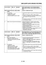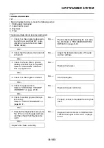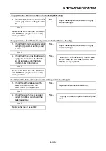
ABS (ANTI-LOCK BRAKE SYSTEM)
8-158
EAS1MC1007
[C-1] DELETING THE FAULT CODES
1. Check:
• Engine stop due to sidestand operation
WARNING
EWA1MC1021
• Make sure to elevate the rear wheel.
• Make sure that there are no persons or ob-
jects in front of the vehicle.
▼▼▼
▼
▼ ▼▼▼
▼
▼ ▼▼▼
▼
▼ ▼▼▼
▼
▼ ▼▼▼
▼
▼ ▼▼▼
▼
▼▼▼
a. Place the vehicle on the centerstand so that
the rear wheel is elevated.
b. Shift the transmission into gear and extend
the sidestand.
c. Turn the main switch to “ON”.
d. Push the “
” side of the start/engine stop
switch, and check that the starter motor dose
not operate. If the starter motor operates,
check the ignition circuit cut-off system. Refer
to “ENGINE STOPPING DUE TO SIDE-
STAND OPERATION” on page 8-3.
e. Turn the main switch to “OFF”.
f. Retract the sidestand.
▲▲▲
▲
▲ ▲▲▲
▲
▲ ▲▲▲
▲
▲ ▲▲▲
▲
▲ ▲▲▲
▲
▲ ▲▲▲
▲
▲▲▲
2. Connect the test coupler adapter “1” to the
ABS test coupler “2”. Refer to “[A-4] THE
ABS WARNING LIGHT COME ON” on page
8-135.
3. Turn the main switch to “ON”.
Fault codes will be displayed in the multi-
function meter right display.
4. Shift the transmission into gear and extend
the sidestand.
NOTICE
ECA1MC1026
If the “
”
side of the start/engine stop
switch is pushed without performing step 4,
the starter motor gear or other parts may be
damaged.
5. Push the “
” side of the start/engine stop
switch “1” at least 10 times in 4 seconds to
delete the fault codes.
6. The multi-function meter right display switch-
es to the normal display and the ABS warning
light flashes in 0.5 second-intervals while the
fault codes are being deleted.
7. Turn the main switch to “OFF”.
8. Turn the main switch to “ON” again.
TIP
If fault codes are still displayed in the multi-func-
tion meter right display, the malfunctions have
not been repaired. Diagnose the malfunctions
using the fault codes.
9. Turn the main switch to “OFF”.
10.Disconnect the test coupler adapter from the
ABS test coupler, and then install the protec-
tive cap onto the ABS test coupler. Deleting
the fault codes is now finished.
TIP
Do not forget to install the protective cap onto
the ABS test coupler.
NOTICE
ECA3P6D014
Since the fault codes remain in the memory
of the ABS ECU until they are deleted, always
delete the fault codes after the service has
been completed.
EAS1MC1008
[C-2] DELETE FUNCTION TEST
1. Check:
• Engine stop due sidestand operation
Refer to “[C-1] DELETING THE FAULT
CODES” on page 8-158.
2. Disconnect the ABS ECU coupler.
3. Connect the test coupler adapter to the ABS
test coupler.
4. Turn the main switch to “ON”.
2
1
STOP
MO
DE
RU
N
STA
RT
1
Содержание FJR1300A(D)
Страница 1: ...2013 SERVICE MANUAL FJR1300A D 1MC 28197 E0 ...
Страница 6: ......
Страница 8: ......
Страница 70: ...SPECIAL TOOLS 1 61 ...
Страница 101: ...LUBRICATION POINTS AND LUBRICANT TYPES 2 30 ...
Страница 104: ...LUBRICATION SYSTEM CHART AND DIAGRAMS 2 33 EAS20410 LUBRICATION DIAGRAMS 5 6 7 1 2 3 4 ...
Страница 106: ...LUBRICATION SYSTEM CHART AND DIAGRAMS 2 35 1 3 2 ...
Страница 107: ...LUBRICATION SYSTEM CHART AND DIAGRAMS 2 36 1 Main axle 2 Drive axle 3 Oil delivery pipe 1 ...
Страница 108: ...LUBRICATION SYSTEM CHART AND DIAGRAMS 2 37 6 5 4 3 2 1 ...
Страница 110: ...LUBRICATION SYSTEM CHART AND DIAGRAMS 2 39 1 2 3 4 5 6 7 8 9 ...
Страница 112: ...LUBRICATION SYSTEM CHART AND DIAGRAMS 2 41 4 5 3 2 1 9 8 6 7 ...
Страница 114: ...COOLING SYSTEM DIAGRAMS 2 43 EAS20420 COOLING SYSTEM DIAGRAMS 3 13 4 5 6 7 7 7 8 1 2 10 9 14 15 16 17 11 12 3 ...
Страница 116: ...COOLING SYSTEM DIAGRAMS 2 45 7 1 2 3 4 5 5 8 9 6 8 9 10 11 12 ...
Страница 122: ...CABLE ROUTING 2 51 Rear brake hose right side view 4 5 6 7 8 9 10 11 1 12 13 14 15 2 3 16 1 A B C F E D ...
Страница 124: ...CABLE ROUTING 2 53 Horn and radiator left side view A B 1 1 2 3 4 5 5 6 C 7 7 8 ...
Страница 128: ...CABLE ROUTING 2 57 Rear fender left side view 2 1 3 4 6 5 7 A C B 8 4 5 4 5 J I K 9 10 1 11 12 13 14 15 D F G H E 16 ...
Страница 132: ...CABLE ROUTING 2 61 Rear fender top view 1 2 3 B C A B ...
Страница 138: ...CABLE ROUTING 2 67 ...
Страница 141: ......
Страница 320: ...CAMSHAFTS 5 19 11 Install Cylinder head cover plate 1 TIP Be sure the UP mark a is facing up New 2 2 a 1 3 a a 1 ...
Страница 360: ...SHIFT SHAFT 5 59 c Tighten both locknuts to specification T R Shift rod locknut 7 Nm 0 7 m kg 5 1 ft lb 1 2 c d a b ...
Страница 377: ...MIDDLE GEAR 5 76 Middle driven pinion gear shim Thickness mm 0 10 0 15 0 20 0 30 0 40 0 50 ...
Страница 428: ...WATER PUMP 6 15 ...
Страница 442: ...AIR INDUCTION SYSTEM 7 13 EAS27040 AIR INDUCTION SYSTEM 1 2 3 5 6 7 8 1 1 2 1 1 3 6 7 8 2 2 3 5 4 ...
Страница 455: ...IGNITION SYSTEM 8 6 ...
Страница 461: ...ELECTRIC STARTING SYSTEM 8 12 ...
Страница 465: ...CHARGING SYSTEM 8 16 ...
Страница 477: ...SIGNALING SYSTEM 8 28 ...
Страница 533: ...FUEL INJECTION SYSTEM 8 84 ...
Страница 551: ...CRUISE CONTROL SYSTEM 8 102 ...
Страница 555: ...FUEL PUMP SYSTEM 8 106 ...
Страница 563: ...ACCESSORY BOX SYSTEM 8 114 ...
Страница 573: ...IMMOBILIZER SYSTEM 8 124 ...
Страница 577: ...ABS ANTI LOCK BRAKE SYSTEM 8 128 ...
Страница 616: ...ELECTRICAL COMPONENTS 8 167 7 1 3 2 18 21 20 19 9 11 12 13 14 15 16 17 6 8 4 5 10 ...
Страница 658: ......
Страница 659: ......
Страница 660: ......


