


CLUTCH
5-54
EAS25290
CHECKING THE CLUTCH MASTER
CYLINDER
1. Check:
• Clutch master cylinder body
Cracks/damage
→
Replace the clutch mas-
ter cylinder.
• Clutch fluid delivery passage
(clutch master cylinder body)
Obstruction
→
Blow out with compressed air.
2. Check:
• Clutch master cylinder
• Clutch master cylinder kit
Rust/scratches/wear
→
Replace the clutch
master cylinder and clutch master cylinder kit
as a set.
3. Check:
• Clutch master cylinder reservoir
Cracks/damage
→
Replace.
• Clutch master cylinder reservoir diaphragm
Damage/wear
→
Replace.
4. Check:
• Clutch hose
Cracks/damage/wear
→
Replace.
EAS25300
ASSEMBLING THE CLUTCH MASTER
CYLINDER
WARNING
EW3P61015
• Before installation, all internal clutch com-
ponents must be cleaned and lubricated
with clean or new clutch fluid.
• Never use solvents on internal clutch com-
ponents.
EAS25310
INSTALLING THE CLUTCH MASTER
CYLINDER
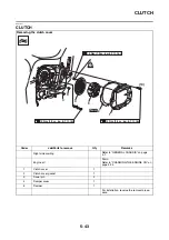
1. Install:
• Clutch master cylinder “1”
• Clutch master cylinder holder “2”
WARNING
EW3P61016
• Install the clutch lever holder with the “UP”
mark facing up.
• Align the end of the clutch lever holder with
the punch mark “a” on the left handlebar.
• First, tighten the upper bolt, then the lower
bolt.
2. Install:
• Copper washers “1”
• Clutch hose “2”
• Clutch hose union bolt “3”
WARNING
EW3P61017
Proper clutch hose routing is essential to in-
sure safe vehicle operation. Refer to “CABLE
ROUTING” on page 2-47.
NOTICE
EC3P61034
When installing the clutch hose onto the
clutch master cylinder, make sure the clutch
pipe touches the projection “a” as shown.
TIP
Turn the handlebars to the left and to the right to
make sure the clutch hose does not touch other
parts (e.g., wire harness, cables, leads). Correct
if necessary.
Recommended clutch component replace-
ment schedule
Piston seal
Every two years
Clutch hose
Every four years
Clutch fluid
Every two years and
whenever the clutch
is disassembled
Specified brake and clutch fluid
DOT 4
T
R
.
.
Clutch hose union bolt
30 Nm (3.0 m·kg, 22 ft·lb)
2
New
Содержание FJR1300A(D)
Страница 1: ...2013 SERVICE MANUAL FJR1300A D 1MC 28197 E0 ...
Страница 6: ......
Страница 8: ......
Страница 70: ...SPECIAL TOOLS 1 61 ...
Страница 101: ...LUBRICATION POINTS AND LUBRICANT TYPES 2 30 ...
Страница 104: ...LUBRICATION SYSTEM CHART AND DIAGRAMS 2 33 EAS20410 LUBRICATION DIAGRAMS 5 6 7 1 2 3 4 ...
Страница 106: ...LUBRICATION SYSTEM CHART AND DIAGRAMS 2 35 1 3 2 ...
Страница 107: ...LUBRICATION SYSTEM CHART AND DIAGRAMS 2 36 1 Main axle 2 Drive axle 3 Oil delivery pipe 1 ...
Страница 108: ...LUBRICATION SYSTEM CHART AND DIAGRAMS 2 37 6 5 4 3 2 1 ...
Страница 110: ...LUBRICATION SYSTEM CHART AND DIAGRAMS 2 39 1 2 3 4 5 6 7 8 9 ...
Страница 112: ...LUBRICATION SYSTEM CHART AND DIAGRAMS 2 41 4 5 3 2 1 9 8 6 7 ...
Страница 114: ...COOLING SYSTEM DIAGRAMS 2 43 EAS20420 COOLING SYSTEM DIAGRAMS 3 13 4 5 6 7 7 7 8 1 2 10 9 14 15 16 17 11 12 3 ...
Страница 116: ...COOLING SYSTEM DIAGRAMS 2 45 7 1 2 3 4 5 5 8 9 6 8 9 10 11 12 ...
Страница 122: ...CABLE ROUTING 2 51 Rear brake hose right side view 4 5 6 7 8 9 10 11 1 12 13 14 15 2 3 16 1 A B C F E D ...
Страница 124: ...CABLE ROUTING 2 53 Horn and radiator left side view A B 1 1 2 3 4 5 5 6 C 7 7 8 ...
Страница 128: ...CABLE ROUTING 2 57 Rear fender left side view 2 1 3 4 6 5 7 A C B 8 4 5 4 5 J I K 9 10 1 11 12 13 14 15 D F G H E 16 ...
Страница 132: ...CABLE ROUTING 2 61 Rear fender top view 1 2 3 B C A B ...
Страница 138: ...CABLE ROUTING 2 67 ...
Страница 141: ......
Страница 320: ...CAMSHAFTS 5 19 11 Install Cylinder head cover plate 1 TIP Be sure the UP mark a is facing up New 2 2 a 1 3 a a 1 ...
Страница 360: ...SHIFT SHAFT 5 59 c Tighten both locknuts to specification T R Shift rod locknut 7 Nm 0 7 m kg 5 1 ft lb 1 2 c d a b ...
Страница 377: ...MIDDLE GEAR 5 76 Middle driven pinion gear shim Thickness mm 0 10 0 15 0 20 0 30 0 40 0 50 ...
Страница 428: ...WATER PUMP 6 15 ...
Страница 442: ...AIR INDUCTION SYSTEM 7 13 EAS27040 AIR INDUCTION SYSTEM 1 2 3 5 6 7 8 1 1 2 1 1 3 6 7 8 2 2 3 5 4 ...
Страница 455: ...IGNITION SYSTEM 8 6 ...
Страница 461: ...ELECTRIC STARTING SYSTEM 8 12 ...
Страница 465: ...CHARGING SYSTEM 8 16 ...
Страница 477: ...SIGNALING SYSTEM 8 28 ...
Страница 533: ...FUEL INJECTION SYSTEM 8 84 ...
Страница 551: ...CRUISE CONTROL SYSTEM 8 102 ...
Страница 555: ...FUEL PUMP SYSTEM 8 106 ...
Страница 563: ...ACCESSORY BOX SYSTEM 8 114 ...
Страница 573: ...IMMOBILIZER SYSTEM 8 124 ...
Страница 577: ...ABS ANTI LOCK BRAKE SYSTEM 8 128 ...
Страница 616: ...ELECTRICAL COMPONENTS 8 167 7 1 3 2 18 21 20 19 9 11 12 13 14 15 16 17 6 8 4 5 10 ...
Страница 658: ......
Страница 659: ......
Страница 660: ......