129
DPX-1000
DPX-1000
E-
8
Installation
■
Pr
ojection ima
g
e
position
F
ollo
w the instr
uctions belo
w to adjust the position of the pr
ojected imag
e on the scr
een.
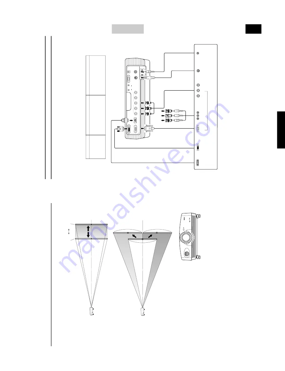
<Adjusting using the zoom>
This f
igure sho
ws the limits within whic
h the zoom function can alter
pr
ojection distance in rela
tion to the scr
een size.
W
ithin these limits, it is
possible to adjust the imag
e so that it f
ills the screen completely
. (See
page 12.)
<Adjusting using the
V
. POS (ver
tical positioning)>
It is possible to adjust the v
ertical position of the pr
ojected ima
g
e on the
scr
een up or do
wn by half the height of the screen.
F
or e
xample
, shifting
V
. POS fully up will bring the lo
wer limit of the
ima
g
e a
b
o
v
e the centerline of the lens. (See pa
g
e 12.)
<Adjusting using the adjuster
s>
When this unit is mounted on a tabletop, the position of the image can be
adjusted by using the adjusters located on the underside of the unit.
Adjust the height by r
ota
ting the mo
v
ab
le part of the tw
o scre
w-type
adjuster
s at the front bottom of the case
.
T
he adjustment r
ange of these
adjuster
s is 3 cm (1-1/4 inch).
Adjust with car
e as loosening them fur
ther
may cause them to separate from the main unit.
■
K
e
ystone
When the unit is mounted a
t an angle to the scr
een, the imag
e will be pr
ojected in a trapezoid manner
. Use the k
eystone functio
n in the
k
eystone section of
4
<SETUP> in the menu to rectify this. (See pag
e 21.)
Te
le
Lens center line
Shifted full
y
do
w
n
Shifted full
y
up
Lens center line
Pr
ojected ima
g
e
W
ide
E-
9
CONNECTIONS
English
DVI
INPUT B
RGB/YP
B
P
R
/YC
B
C
R
D4 VIDEO
G/Y
B/P
B
/C
B
R/P
R
/C
R
INPUT A
HD/SYNC
VD
OUT
IN
REMOTE
RS-232C
S-VIDEO
V
IDEO
TRIGGER OUT
G
/
YR
/
P
R
/
C
R
B
/
P
B
/
C
B
◆
Note
◆
•
Make sure to matc
h the
Y/P
B
/P
R
or
Y/C
B
/C
R
of the A/V component and this unit when connecting a component to INPUT A compo-
nent jac
ks.
Also,
ref
er to the operation instructions f
or the A/V component.
HD/SYNC and
VD need to be connected f
or RGB video
signals in some cases.
Connecting the unit
•
Mak
e sur
e that the po
wer of this unit and all other components is turned of
f bef
or
e making an
y connections.
•
Some components ha
v
e dif
ferent connection methods and connector names.
Refer to the operating instructions for each component that you wish to connect.
•
Plug the unit in correctly to pre
v
ent it from cr
ea
ting noise or other problems.
■
Connecting A/V components
As sho
wn in the illustra
tion belo
w
, ther
e are 6 types of connections pro
vided on this unit for connection to
A/V components.
F
ollo
w the instr
uctions on the f
igure belo
w to connect
A/V video outputs from other components to this unit using the cor
rect c
ab
les and
adapters.
D connector cable
D-sub monitor
cab
le
BNC cab
le f
or component
connection
Pin/BNC
adapter
s
Pin cab
le
Video pin cab
le
S video cab
le
D1—4 output
connector
s
Pin jac
ks
D-sub
Component/RGB video output connector
s
Ima
ge output fr
om A/
V
components
BNC jac
k
s
S
video output
jac
k
Video output
jac
k
Input
VIDEO
S-VIDEO
INPUT A
INPUT B
D4 VIDEO
DV
I
Signal type
Composite video
S video
Component video/RGB video
Component video/RGB video
Component video
Component video/RGB video (digital)
Connector type
Pin jack
Mini DIN connector
BNC connector x 3
—
5
D-sub 15 pin
D connector
D
VI connector
D
V
I cab
le (digital)
D
V
I output
connector
Содержание DPX-1000
Страница 40: ...DPX 1000 DPX 1000 40 MEMO ...


