130
DPX-1000
DPX-1000
E-
10
DVI
INPUT B
RGB/YP
B
P
R
/YC
B
C
R
D4 VIDEO
G/Y
B/P
B
/C
B
R/P
R
/C
R
INPUT A
HD/SYNC
VD
OUT
IN
REMOTE
RS-232C
S-VIDEO
V
IDEO
TRIGGER OUT
■
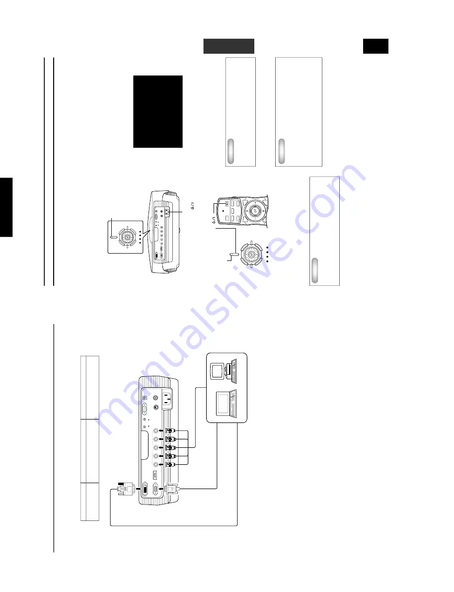
Connecting to a computer
There are thr
ee w
a
ys of connecting a computer
, as listed belo
w
. Please use the cor
rect type of cab
le f
or the connector when mak
ing
connections.
Connecting the unit
◆
Note
◆
•
Ref
er to see
2
<SIGNAL> in the menu described on pa
ge 19 f
or detailed settings f
or the type of ima
ge signal input.
D
VI cab
le (Digital)
D-Sub monitor
cab
le
BNC monitor cab
le
Monitor output terminal
D
V
I output terminal
Computer
Input
INPUT A
INPUT B
DV
I
Signal type
RGB Analog
RGB Analog
RGB Digital
Connector type
BNC jack x 5
D-sub 15 pin
D
VI connector
E-
11
BASIC OPERATION
English
Basic Operations
■
T
urning on the po
wer
Be sure to remo
v
e the lens co
v
er bef
or
e using this unit.
1.
Plug the supplied po
wer cor
d into the A
C
inlet on the
rear of the DPX-1000,
then plug the cor
d into the wall
outlet.
The ST
ANDBY/ON indicator will turn orang
e
.
2.
Press the ST
ANDBY/ON b
utton (The
b
utton on
the remote contr
ol).
The indicator will b
link green and
the lamp inside the unit will light up, in preparation
for
pr
ojection.
◆
Note
◆
•
There are ST
ANDBY/ON indicator
s located on the fr
ont panel
and the contr
ol panel of the main unit.
3.
After appr
o
ximatel
y 35 seconds,
the indicator will
stop b
linking,
indicating that preparations f
o
r
pr
ojection are complete
.
Impor
tant
•
Be sure not to disconnect the po
wer cor
d while the
po
wer ST
ANDBY/ON indicator is green,
or b
linking
green.
This can cause significant dama
g
e to the
lamp and ma
y result in a shor
ter lamp lif
e or failure
.
ST
ANDBY/ON indicator
DVI
INPUT B
RGB/YP
B
P
R
/YC
B
C
R
D4 VIDEO
G/Y
B/P
B
/C
B
R/P
R
/C
R
INPUT A
HD/SYNC
VD
OUT
IN
REMOTE
RS-232C
S-VIDEO
VIDEO
TRIGGER OUT
ST
ANDBY
/
ON
SETTING
LAMP
COVER
TEMP
F
AN
P
A
TTERN
ESCAPE
MENU
INPUT
ASPECT
ST
ANDBY/ON indicator
A
C
inlet
INPUT
MENU
PA
T
T
IRIS
AUTO
SETTING
ASPECT
ZOOM
FOCUS
V
. POS
ESCAPE
ST
ANDBY
/
ON
SETTING
LAMP
COVER
T
EMP
F
AN
P
A
TTERN
ESCAPE
MENU
INPUT
ASPECT
ST
ANDBY ON (
)
■
T
urning off the po
wer
1.
Press the ST
ANDBY/ON b
utton when finished using
this unit.
There will be a messa
g
e to conf
irm tha
t y
ou wish to tur
n the
unit of
f. Press the
ST
ANDBY/ON
b
utton once mor
e to conf
irm
that you wish to do so.
T
he lamp will switch to a half-lit state,
and the f
an continues f
or roughly 2 minutes to cool the lamp.
Dur
ing this time,
the ST
ANDBY/ON indica
tor b
links orange
.
Y
ou cannot turn the unit on ag
ain by pr
essing the
ST
ANDBY/
ON
b
utton during this time.
◆
Note
◆
•
The lamp ma
y b
link when in the half-lit state
. This is not a
lamp failure
.
2.
Once cooling is completed,
the ST
ANDBY/ON
indicator will cease b
linking,
becoming a stead
y
orang
e
.
Impor
tant
•
Do not disconnect the po
wer cor
d when the fan is
going and the ST
ANDBY/ON indicator is b
linking
orang
e
. This could dama
ge the lamp and result in
shor
ter lamp lif
e or lamp failure
.
3.
Replace the lens co
ver and disconnect the unit fr
om
the po
wer outlet if y
ou do not plan to use it f
or a long
time
.
Impor
tant
•
Condensation ma
y appear on the unit if the
temperature of the surr
ound en
vir
onment c
hang
es
quic
kl
y
. Condensation ma
y also cause the
pr
ojected ima
ge to be c
loud
y
. Switc
h off the unit
po
wer
until
the
condensation
disappear
s.
Switc
hing the unit on when condensation is
present ma
y dama
ge the unit.
Press again for standby
This section descr
ibes the basic oper
ation of the DPX-1000 once installa
tion and connection ha
v
e been completed. It is necessar
y to mak
e
detailed settings in the menu described later so that the DPX-1000 is correctly set for the mounting, screen, input signals, an
d other
conditions of its installation. F
ollo
w the steps descr
ibed in this section to car
ry out these pr
ocedur
es.
Содержание DPX-1000
Страница 40: ...DPX 1000 DPX 1000 40 MEMO ...


