Output Patching
79
DM2000 Version 2—Owner’s Manual
Output Patching
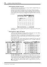
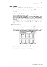
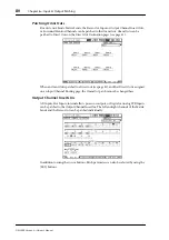
Signal sources for the Slot Outputs, Omni Outs, Output Channel Inserts Ins, Direct Outs,
2TR Digital Outputs, and GEQs are selected on the Output Patch pages, which are selected
by using the DISPLAY ACCESS [OUTPUT PATCH] button. Use the cursor buttons to select
the patch parameters, use the Parameter wheel or INC/DEC buttons to select a source, and
press [ENTER] to set.
Depending on the patch page, patch parameters display either Short Channel or Short Port
names. The Long Channel or Port name of the currently selected patch parameter is dis-
played in the upper-right corner of each page.
Signal sources can also be selected by using the Patch Select Window (see page 83). Insert
Ins, Insert Outs, and Direct Outs can also be patched by using the Encoders (see page 83).
See page 290 for a complete list of output patch sources. See page 297 for a list of initial out-
put patches.
Output Patch settings can be stored in the Output Patch library, which contains 1 preset
memory and 32 user memories. See “Output Patch Library” on page 167 for more informa-
tion.
Patching Slot Outputs
Bus Outs, Aux Sends, Matrix Sends, the Stereo Out, Input or Output Channel Insert Outs,
or Surround Monitor Channels can be patched to the Slot Outputs. Slot Outputs can be
patched to Direct Outs on the Direct Out Destination pages (see page 81).
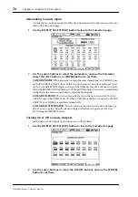
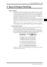
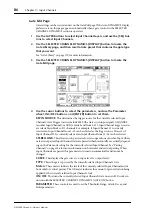
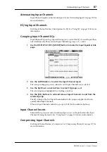
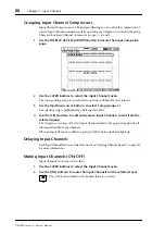
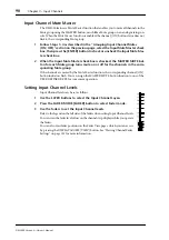
The Slot Output Patch parameters for the six Slots are arranged into three pages. The Slot
1–2 Output Patch page is shown below. The layout of the other two pages is the same.
When a Slot Output is patched to a Direct Out (see page 81), and that Direct Out is assigned
on an Input Channel Routing page, the Slot Output patch cannot be changed here. If the
higher sampling rate (88.2 kHz/96 kHz) data format is set to Double Channel mode, the
Slot’s even channel patch is disabled and cannot be changed.

