Welcome to the world of the AW2816
32
Chapter
2
Operation section
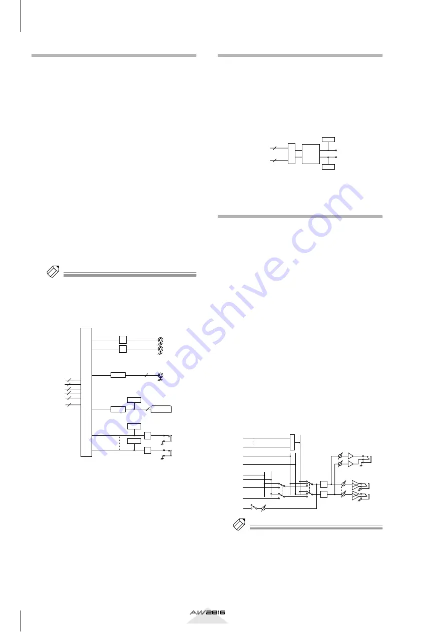
Output patch
This section assigns output signals to OMNI OUT
jacks 1–4, the STEREO OUT jacks, DIGITAL STEREO
OUT jack, and an I/O card installed in the OPTION I/
O slot. The following output signals can be selected.
• STEREO
The output signal of the stereo bus routed through
the stereo output channel.
• BUS 1–8
The output signals of buses 1–8.
• AUX 1–6
The output signals of AUX buses 1–6.
• CH DIRECT OUT 1–8
The direct output of input channels 1–8.
• INSERT SEND
Insertion outputs for inserting internal effects into
each channel.
• RECORDER DIRECT OUT 1–16
The direct output of tracks 1–16 of the recorder sec-
tion.
Tip!
In general, these output signals can be assigned to any
output jack or output channel. For the STEREO OUT
jacks and DIGITAL STEREO OUT jacks, two adjacent
odd-numbered
→
even-numbered signals will always
be assigned.
Internal effects 1/2
With the AW2816’s default settings, the outputs of
AUX buses 5/6 are patched to the inputs of internal
effects 1/2 respectively. Also, the outputs of effects 1/2
are assigned to return channels 1/2.
If desired, you may defeat these assignments and
insert internal effects 1/2 into desired channels, or use
AUX buses 5/6 and return channels 1/2 for other pur-
poses.
Monitor output/headphone out-
put
For monitoring purposes, the AW2816 provides
MONITOR OUT jacks and a PHONES jack. The type
of signal that is output from these jack will change as
follows, depending on the state of the AW2816.
1
When the AW2816 is in the default state
The signal of the stereo output channel will be out-
put directly to the MONITOR OUT jacks/PHONES
jack.
B
When the [SOLO] key is on
The signal of the channel selected by the [ON] key
will be sent to the SOLO bus, and will be output
from the MONITOR OUT jacks/PHONES jack.
During this time, other signals will be muted.
C
When the [CUE] key is on
The direct output signal of the track selected by
the REC TRACK SELECT [1]–[16]/[ST] keys will be
output from the MONITOR OUT jacks/PHONES
jack. During this time, other signals will be muted.
D
When the internal metronome is on
The metronome signal will be mixed into the out-
put signals of (
1
)–(
3
).
Tip!
• The MONITOR OUT jacks and PHONES jack always
output the same signal. However, the level adjust-
ment is independent: the output level of the MONI-
TOR OUT jacks is adjusted by the [MONITOR
OUT] control, and the output level of the PHONES
jack is adjusted by the [PHONES] control.
• If both the [SOLO] key and the [CUE] key are turned
on, only the [CUE] key will be valid.
OMNI OUT
DIGITAL STEREO
OUT
2
DITHER
STEREO OUT
–10dBV
R
L
DA
DA
RECORDER DIRECT
OUT 1~16
8
6
8
CH DIRECT OUT1~8
STEREO
BUS1~8
AUX1~6
2
INSERT SEND
30
16
DA
X 4
0dB
DA
SLOT OUT
8
OPTION I/O SLOT
METER
METER
METER
COAXIAL
DITHER
OUTPUT PATCH
EFFECT
X 2
EFFECT
EFFECT1/2
SELECT
AUX5(EFF1),
AUX6(EFF2)
INSERT SEND
2
30
(EEF)
(EEF)
METER
METER
SOLO R
MIXER
SOLO Logic
RECORDER
TRACK CUE
Logic
SOLO L
RECORDER
DIRECT OUT 1
RECORDER
DIRECT OUT 16
+4dB
L
R
MONITOR
OUT
MONITOR
PHONES
PHONES
DA
METRONOME
ATT
ON
STEREO L
STEREO R
RECORDER ST Trk
DIRECT OUT L
RECORDER ST Trk
DIRECT OUT R
DA
SELECT


