


285
Reference section
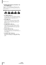
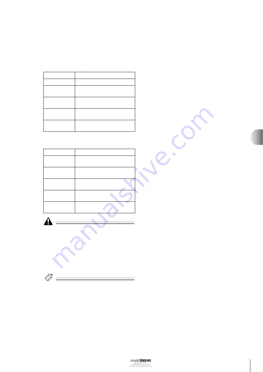
If you specify an output jack/output channel as an
insert send connector for connecting an external
effect to a certain channel, the displays in the Patch
OUT page will change as follows. These displays indi-
cate the insert send that has been patched to that out-
put jack/output channel.
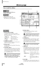
■
OMNI OUT ASSIGN (
1
)/OPTION I/O SLOT
OUT ASSIGN (
2
) areas
■
D.ST OUT ASSIGN (
3
)/ST OUT ASSIGN (
4
)
areas
• When you change the setting in the Patch OUT page
for a output jack/output channel that is patched to
an insert send, a popup window will ask you whether
you want to cancel that patch.
• It is also possible to display insert sends that are not
patched to an output jack/output channel. However
in this case, the insert send will be grayed, and no
signal will be sent. (The operation of assigning an
output jack/output channel to an insert send can be
performed only in the VIEW screen CH View page.)
Tip!
• For details on operations in the Patch OUT page,
• For details on how to insert an external effect into a
channel, refer to page 78.
Display
Signal type
I-I 1–I-I 8
Insert send for input channel 1–8
I-M 1–I-M 16
Insert send for monitor channel
1–16
I-R1L/I-R1R
Insert send for return channel 1 L
or R
I-R2L/I-R2R
Insert send for return channel 2 L
or R
I-STL/I-STR
Insert send for stereo output
channel L or R
Display
Signal type
I-I 1/2–I-I 7/8
Insert send for input channels 1/
2–7/8
I-M 1/2–I-M
15/16
Insert send for monitor channels
1/2–15/16
I-RT1 L/R
Insert send for return channel 1
(L/R)
I-RT2 L/R
Insert send for return channel 2
(L/R)
I-ST L/R
Insert send for stereo output
channel (L/R)
PA
TCH scr
een