VX-7R O
PERATING
M
ANUAL
85
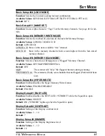
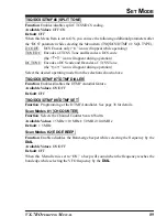
Basic Setup #10
[
LOCK MODE
]
Function
: Selects the Control Locking lockout combination.
Available Values
: KEY/DIAL/KEY+DIAL/PTT/KEY+PTT/DIAL+PTT/ALL
Default
: KEY
Basic Setup #11
[
NAME SET
]
Function
: Stores Alpha-Numeric “Tags” for the Memory channels. See page 48 for de-
tails.
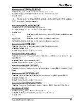
Basic Setup #12
[
MEMORY WRITE MODE
]
Function
: Selects the method of selection of channels for Memory Storage.
Available Values
: LOWER CH/NEXT CH
Default
: LOWER CH
LOWER CH: Stores in the next-available “free” channel
NEXT CH:
Store in the memory channel which is next-highest from the last-stored
memory channel.
Basic Setup #13
[
MEMORY SCAN MODE
]
Function
: Selects what action will happen on a “flagged” Memory Channel.
Available Values
: OFF/SKIP/PREFERENTIAL
Default
: OFF
SKIP:
The scanner will “skip” the flagged channels during scanning.
PREFERENTIAL: The scanner will only scan channels that are flagged (Preferential Scan
List).
Basic Setup #14
[
HYPER WRITE
]
Function
: Enables/disables the Hyper Memory Write feature
Available Values
: ENABLE/DISABLE
Default
: ENABLE
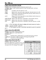
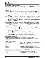
Display Setup #1
[
BUSY LED
]
Function
: Enables/disables the BUSY LED (“STROBE”) while the Squelch is open.
Available Values
: ON/OFF
Default
: ON (“STROBE” lights up when the Squelch is open)
Display Setup #2
[
CONTRAST
]
Function
: Setting of the Display contrast level.
Available Values
: 1 ~ 10
Default
: 7
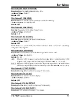
Display Setup #3
[
DIMMER
]
Function
: Setting of the Display brightness level.
Available Values
: 1 ~ 12
Default
: 10
S
ET
M
ODE


